Hi all! I’m really busy this year so I can’t post all the projects where I’m involved. Here’s one of the design I do last year for a client. He wants to measure the voltage of a car battery and set a couple of alarms when voltage falls below a defined values. Also, he wants to put the device in the relay box of the car, so the design needs to have a relay form factor to easy integration. So, after a couple of iterations, here’s the final design of the battery monitor.
The project start around a year ago. The client wants a device to integrate in the relay box of some vehicles to monitor the voltage of the battery (12V nominal value). He wants two alarms at two different voltages. The alarm output will activate other external relays for advertising the low level of the battery, so I use a couple of small SSR for this outputs. Also he wants to configure the time to enable / disable alarms: once the device detect a voltage lower or higher than configurated values, the device needs to wait some time (configurable) before actívate or desactivate the alarms.
- PROTOTYPES
Here’s the first proof of concept, with components I’ve got at home and one afternoon of work;
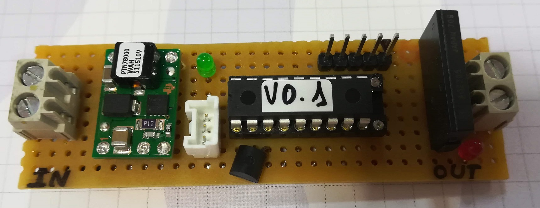
Mains components of this board are:
- PTN78000WAH: 1.5-A wide input adjustable switching regulator, to obtain 5V from 12V input. Obviously oversized and cost – prohibited for this design.
- PIC16F88: A small 8-bit microcontroller from Microchip, to implement all the logic. Expensive and old device but it allows me start with the code. For this I use the mikroC PRO for PIC compiler and the mikroProg programmer, both from mikroe company. On my previous post I cover how to make compatible this programmer with the PicKit 3 programmer from Microchip.
- AQZ205: Solid-State relay. AC/DC dual use, with 100V load voltage and 4 amps load current. Again oversized but perfect for the demo, allowing the client to connect a external relay without problems to activate it. To test the board, I only put one SSR on it.
- To measure the battery voltage, I use a simple network divider with a low pass filter and internal ADC of the PIC16F88.
After some test with the client, he gives me the OK to go on. Proof of concept was fine but now I need to adjust all the components as much as I can to have a device with adjusted costs. I make a new prototype with the new components (and the two SSR relays):
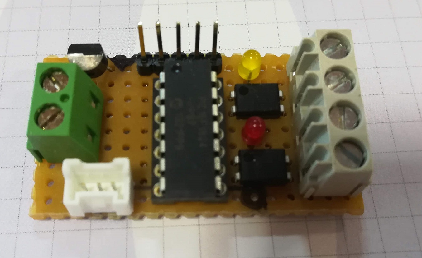
The new components I use on this version are:
- MC78M05CDTRKG: 500-mA Fixed Output Linear Regulator. Input voltage goes up to 35V and the consumption of the board is really small, so with a 500mA output current is more tan enough.
- PIC16F1824: A new device (for me) from Microchip. Same 8-bit architecture but with many peripherals and under 1 eur /piece. Interesting for this poject: internal oscillator (I use 8Mhz freq), ADC on any GPIO pin and internal voltage reference (selectable between 1.024V, 2.048V or 4.096V). On memory stage, it has 4K words and 256 RAM bytes, enough for the application.
- AQY211EH: SSR with reinforced isolation of 5kv. Output ratings are 30V / 1A, so perfect to connect a external relay.
- VERSION 1.0
Test with this board are also OK, so I design a PCB with all. Well, really I design two PCB’s. One for the electronics and another one for the base, where goes the faston connectors.
The schematic of the control board is here: DSN_CONTROL_BATERIA_V01. I add a MOSFET on the input stage to protect the device against polarity inversion when connect the battery. Network resistors are configured to measure up to 15V, adjusting this voltage to maximum 4.096V input voltage on PIC using internal voltage reference (FVR). I also add a user led (D1) and two leds on series with the SSR input that lights when SSR is activate. I also put a connector for microcontroller serial port, I use it on debug stage, to send ADC values and check the accuracy of the measurement.
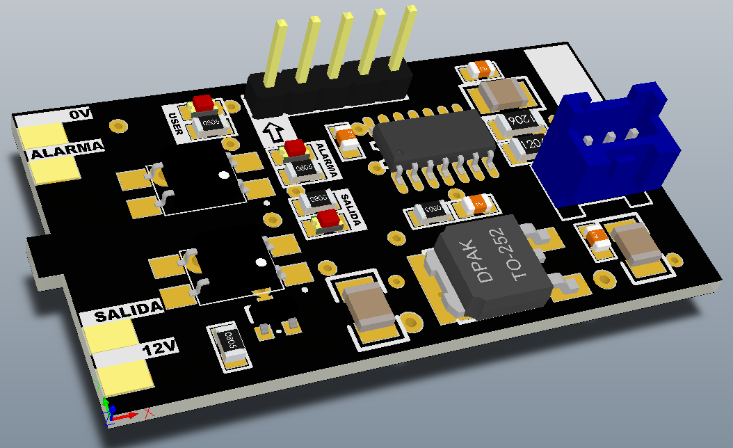
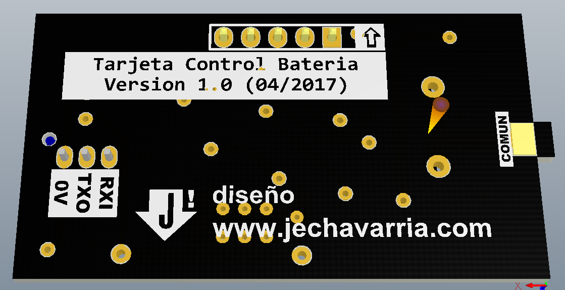
As you can see, on the top right of the board (TOP LAYER) there’re four pads, and there’s another pad in the middle right of the bottom layer. These pads are for soldering the base board and have the automotive relay form factor.
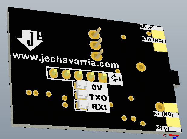
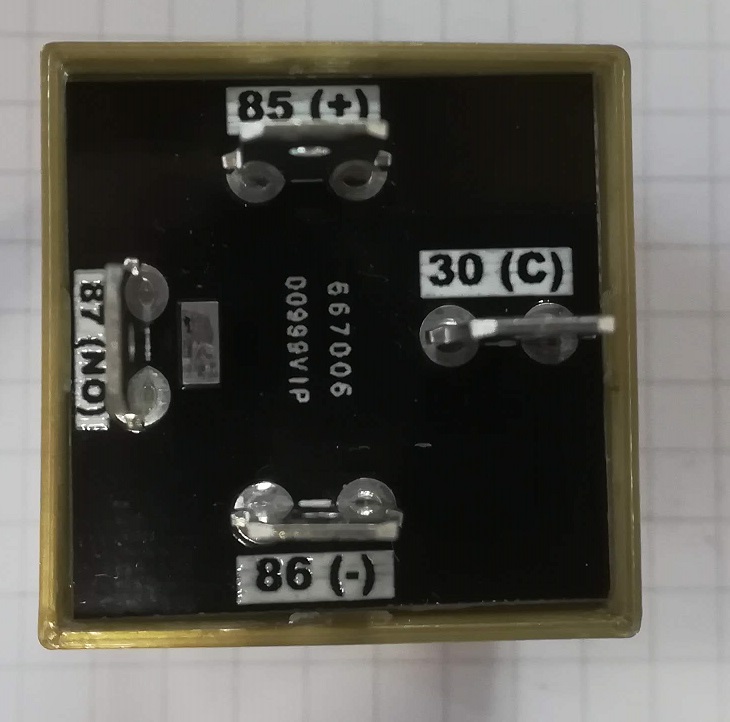
About this base board, schematic is really simple and is here: DSN_BASE_RELE_5P_V01. I use standard 5-pin configuration for the signals:
- Pin 85: 0V (negative from battery)
- Pin 86: 12V (positive from battery)
- Pin 30: Common (positive or negative)
- Pin 87: SSR Out #1
- Pin 87A: SSR Out #2
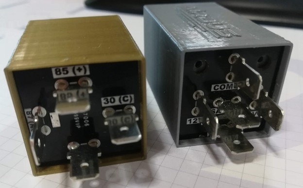
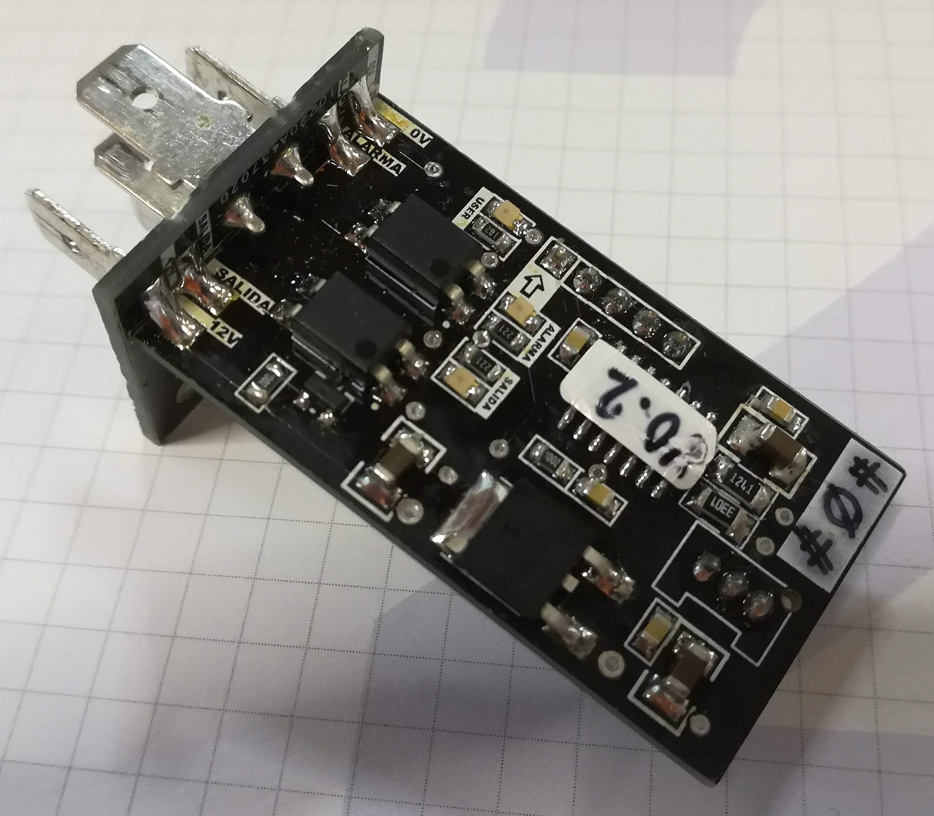
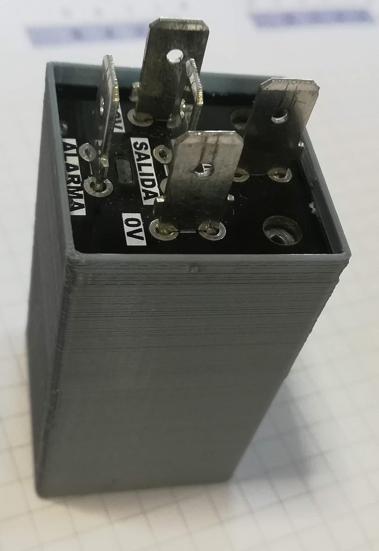
Here’s a link with useful info about relay pinouts. And here are some photos of the boards assembled:


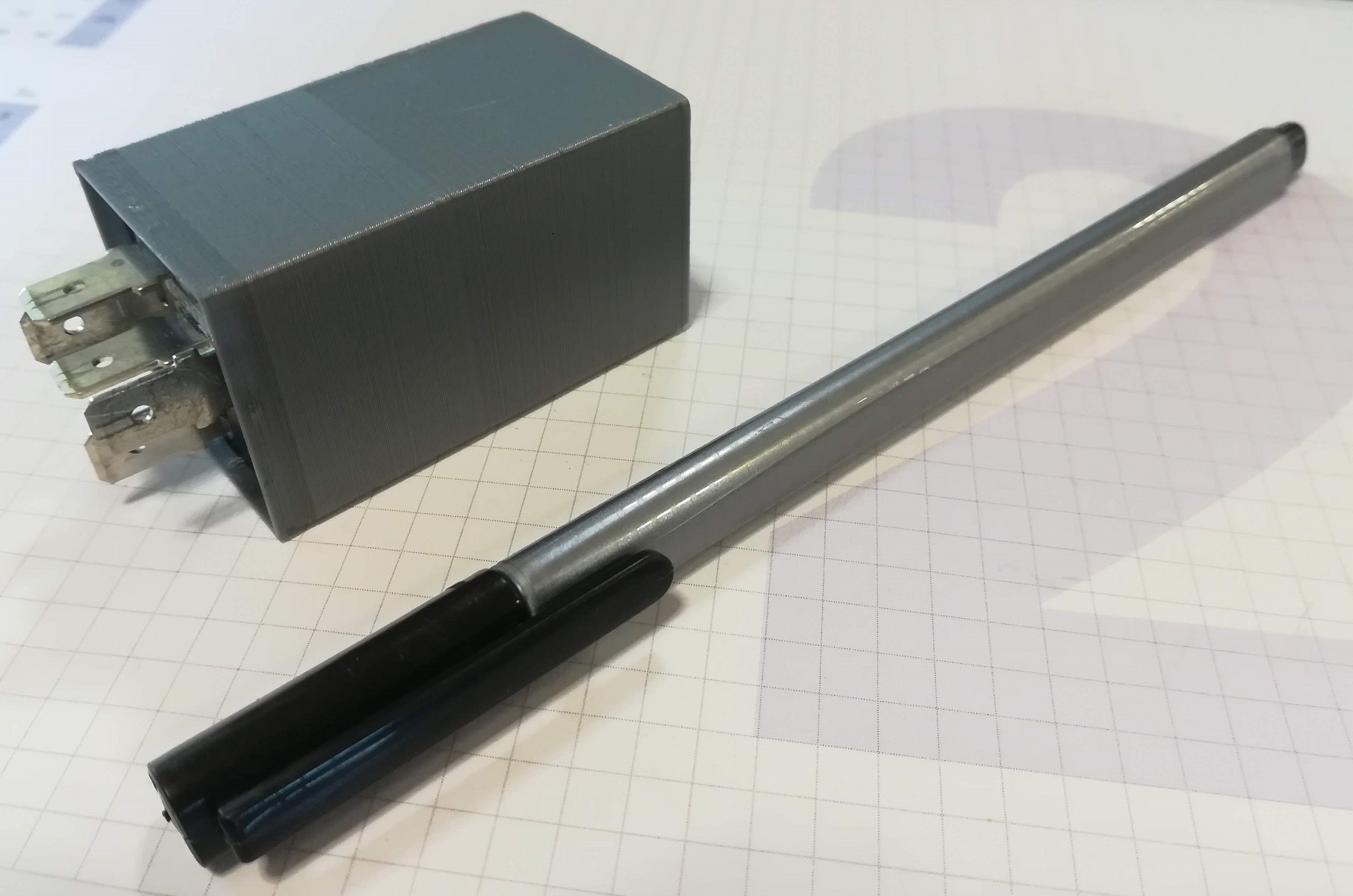
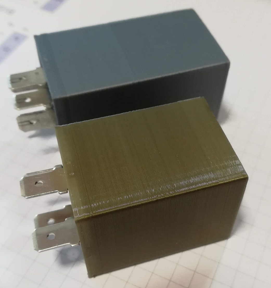
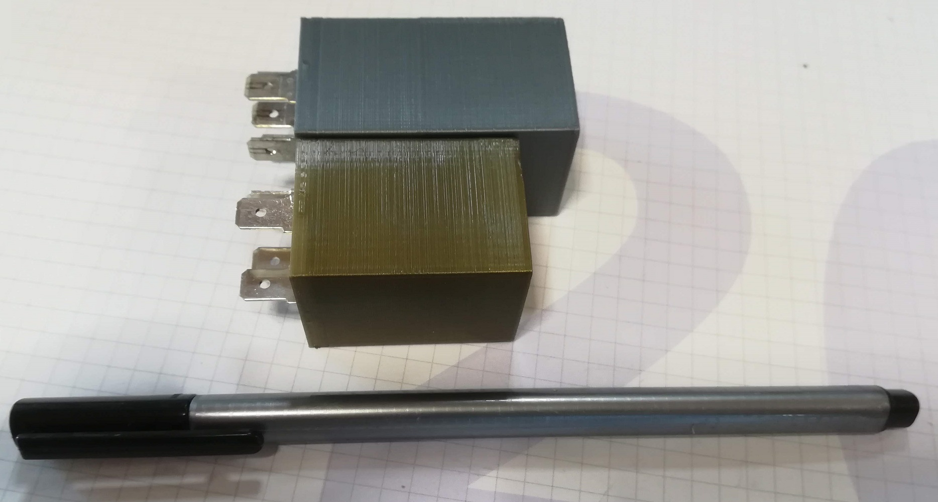
Case for the relay is custom made, designed by a good friend and print on a 3D printer. Dimension of this case are 28x28x52 mm: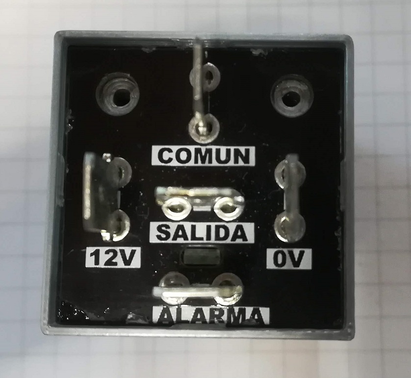
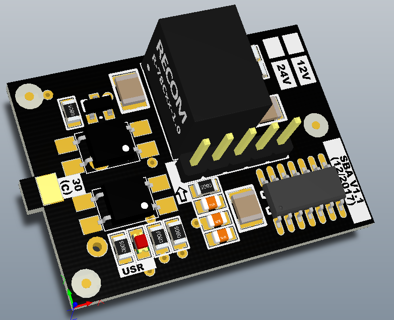
- VERSION 1.1
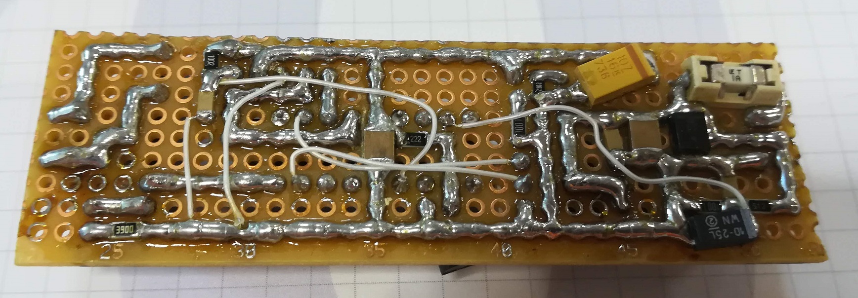
Version 1.0 works fine under the client specs. After a couple of months working well, client ask for a modification. Now he wants to measure battery voltage up to 24V. The problem with actual setup is that linear regulator needs to dissipate a lot of power, so it will be hot and hot….and this is not good for a device that goes on a vehicle. So, I decide to change linear regulator with a switched one. I choose the RECOM R-78E-0.5. Its a low cost switching regulator, with a efficiency up to 95% and pin compatible with 78 series regulators. Input voltage range goes from 7 to 28VDC. Output specs are 5VDC and 0.5amps, and efficiency goes to 82% (minimum VIN) to 92% (maximum VIN). So with this regulator I can cover both models, 12V and 24V battery voltage monitor. The only difference between two models are sensing resistors, adapted on both cases to 4.096V maximun ADC input. I also remove the leds to know if relay are active or not. At the end the board goes on a box and nobody will see it. New schematic can be downloaded here: DSN_CONTROL_BATERIA_V1.1. On the PCB side, I change the side of the board (now is shorter). Here’s the previous board model:
And he’re the assemble board (3pcs):

On the PCB side I also move all the components from bottom side (version 1.0) to top side (version 1.1):

Case is again custom made, now dimensions are 28x28x40 mm (12mm shorter tan V1.0 versión). And for this new version I only use the 4 – pin relay type, so pin 87A (SSR Out #2) is not included. Is not included on the base relay but is on the schematic, so if in the future client needs it, I only need to manufacture the 5 – pin base:
And finally, a photo where you can see all the work behind it: all the prototypes and PCB boards designed and developed until now:

For the moment, that’s the actual version that’s working for around six months without knowing issues. About the software, I can’t post it here due an ageement with the client. I can post all the hardware parts but nothing about sw.


This post is also available in: Spanish
Pingback: Monitoreo de la batería del vehículo en un factor de forma de relé automotriz - Calendae - Calendae | Informática, Electrónica, CMS, Ciberseguridad
Hi,
nice project, I’m doing something similar,
do you have a link or the part number of those connectors?