serial star

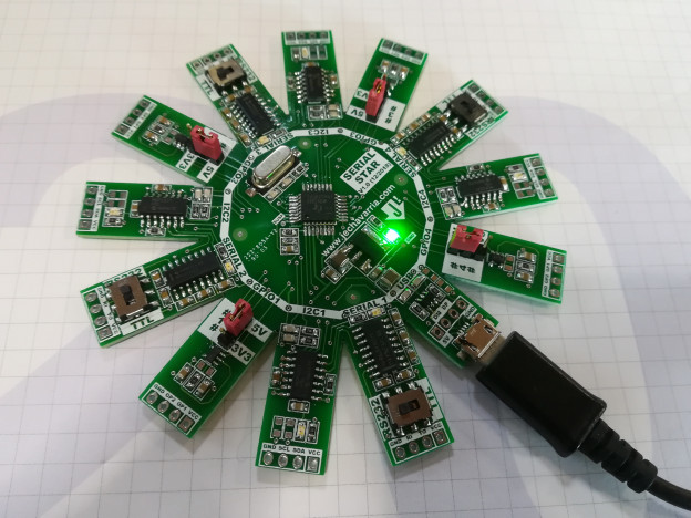
Serial Star, a 4 in 1 USB Serial and I2C Converter

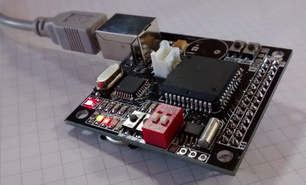
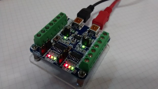
Hi all! Here’s one of the last board I design the last year. On 2016, I develop the Dual USB Serial and I2C Converter board. Although this board works fine, it has a couple of lacks. First one, is that to use the both converters, you need two free USB ports. Is a minor problem today with USB hubs, but you need the hub and also two USB wires. And the other problem is that this board uses mini-USB connectors. Of course today you can still find it, but aren’t as common as the micro-USB wires. For this two reasons, I decide to upgrade the board, add the micro – USB connector and put a USB hub inside it. Because I choose a 4-port USB hub, I use also 4 USB serial converters. With some addons, you can select power supply value (5V, 3V3), serial levels (TTL, RS232) and GPIO functions in an independent way for each converter. So, let’s see how works this USB Serial Star, a 4 in 1 USB to Serial and I2C Converter.

Continue reading

  • Twitter
  • del.icio.us
  • Digg
  • Facebook
  • Technorati
  • Reddit
  • Yahoo Buzz
  • StumbleUpon
Battery Monitor

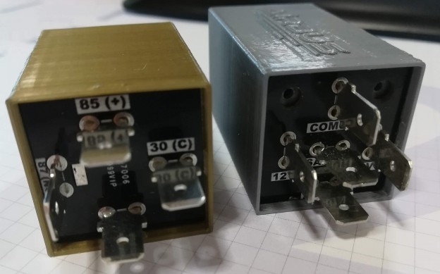
Battery monitor on a automotive realy form factor

Hi all! I’m really busy this year so I can’t post all the projects where I’m involved. Here’s one of the design I do last year for a client. He wants to measure the voltage of a car battery and set a couple of alarms when voltage falls below a defined values. Also, he wants to put the device in the relay box of the car, so the design needs to have a relay form factor to easy integration. So, after a couple of iterations, here’s the final design of the battery monitor.

Continue reading

  • Twitter
  • del.icio.us
  • Digg
  • Facebook
  • Technorati
  • Reddit
  • Yahoo Buzz
  • StumbleUpon
MikroProg to Pickit 3 Adapter

Mikroprog to Pickit 3 adapter

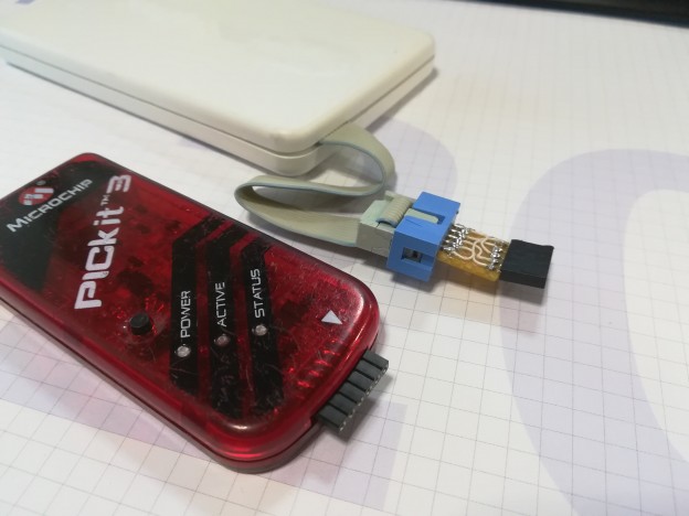
Hi all! After a really busy months, I come back with a small tip. I start again work with PICs some years ago, and since then, I usually use the Pickit 3 programmer from Microchip. It’s a really great tool, with official support, online updates, and I never have a problem with it. But a couple of years ago, I discover the Mikroe products, both compiler for PIC and the programmer they have to program more tan 1000 PIC microcontrollers,  the Mikroprog programmerMikroProg to Pickit 3 adapter

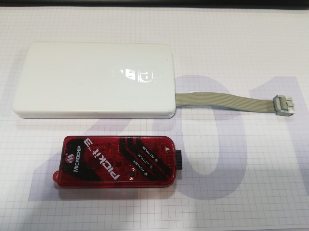
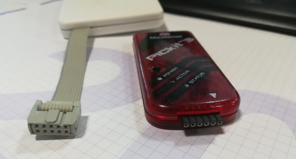
Mikroprog is bigger in size than Pickit3, and comes with a flat 10-pin wire assemble inside the box, so you can’t remove this wire. Pickit 3 has 6-pin female connector just to plug it on the board header for programming.

Both devices has the same USB connector for PC management: USB mini:

Mikroprog to Pickit3 adapter

The problem with this two programmers is the programming connector. As you can see in the following image, both programmers has different connectors and pinout for programming:

MikroProg to Pickit 3 adapter

The pinout of the programmers are shown on the next image: on the left side, Pickit 3 pinout and on the right side, Mikroprog pinout:

MikroProg to Pickit 3 adapter

You can find more technical info about these programers here and here.

So, to use old boards thas has Pickit 3 header with Mikroprog programmer, you definitively need an adapter to have the signals on the same order. Is really simple to implement, just need to cross the signals. Here’s the schematic of the adapter:mikroprog to pickit3 adapter

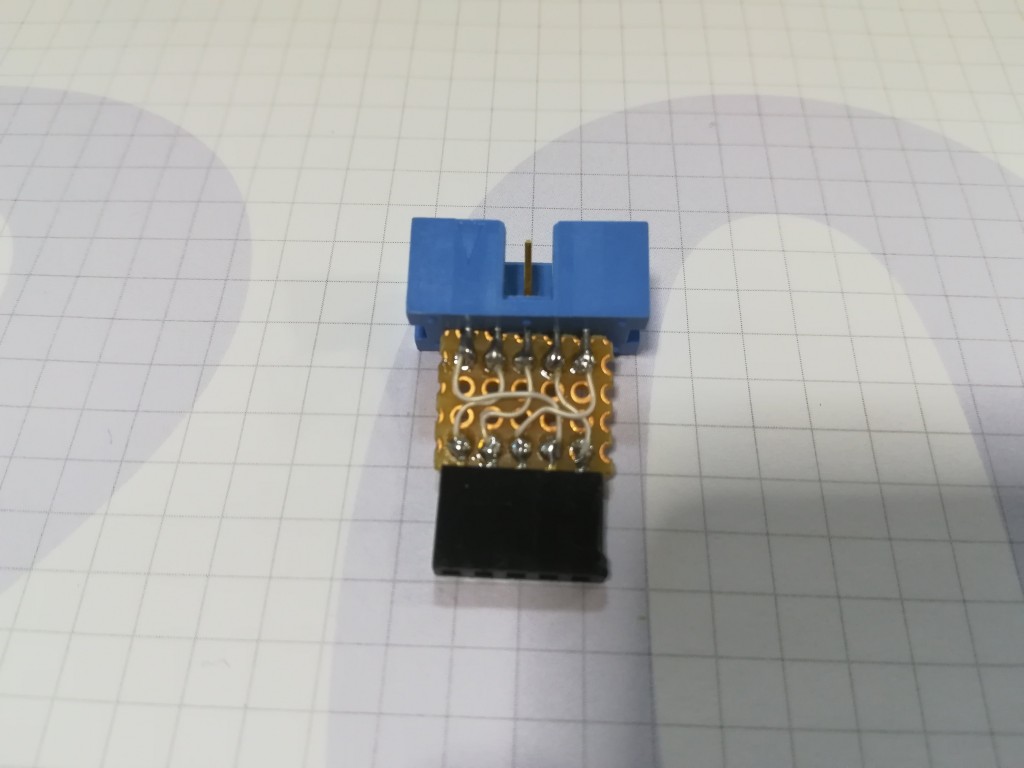
With the connectors and a small piece of prototype board, it just take 10 mins to make it one:

MikroProg to Pickit 3 adapter

So, with this simple adapter you can use both programmers on boards that have a Pickit3 programming header.

  • Twitter
  • del.icio.us
  • Digg
  • Facebook
  • Technorati
  • Reddit
  • Yahoo Buzz
  • StumbleUpon
Revisiting the DSETA board with an AT89C51ED2

Revisiting the DSETA board with an AT89C51ED2

Hi all!

I’m very busy last months working on new boards and projects, sorry for the delay!

Some months ago I review the DSETA board due the obsolescence of the microcontroller. I use this board in some projects succesfully. But when I try to manufacture a batch of this boards, I found that the microcontroller (AT89C51RE2) was obsolete. So, the board needs an update to change the microcontroller and maintain most of the features that it has. Now that Microchip buys Atmel, obsolescence and samples will not be a problem.

To replace the RE2 microcontroller, I choose one very similar, the AT89C51ED2 microcontroller. Mainly because it shares most of features with the old one and footprint and pinout is almost the same, so replacement is relatively easy to do.

Come in and you can see the new board features, changes and more!!

Continue reading

  • Twitter
  • del.icio.us
  • Digg
  • Facebook
  • Technorati
  • Reddit
  • Yahoo Buzz
  • StumbleUpon
DIY Led Tweezers

DIY Polarity Led Tweezers

I usually assemble by hand all the boards I make. I use SMD components, especially in 0805 format for resistors, capacitors and leds. With the last ones, I always have the same problem: I need to check the polarity of it, to ensure that I assemble on the right way. To do it, I need the multimeter, select the diode position and test the led’s for the right polarity. Because on the assembly process I don’t usually the multimeter, why don’t make a tweezers to test the led’s? It’s an easy and very cheap project, and you’ll have a usefull tool when assembly boards. Here’s the result, after a couple of hours working on it ;).

Continue reading

  • Twitter
  • del.icio.us
  • Digg
  • Facebook
  • Technorati
  • Reddit
  • Yahoo Buzz
  • StumbleUpon
FONA808 PC Interface

FONA808 USB Interface

Hi! First of all, Happy New Year 2017! I hope all of yours starts the new year with good intentions. The mine one is write frequently here. Family and work don’t let me much free time but I’ll try it!

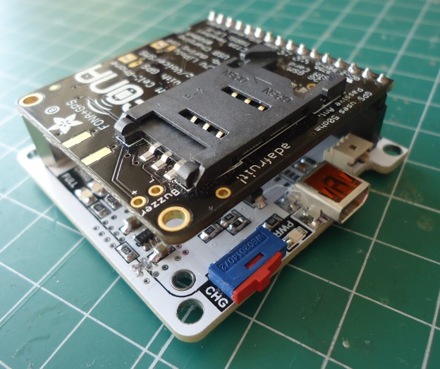
For several months I’m working with FONA808 modules from Adafruit to make a portable, web-based locating system. This modules are based on the SIM808 module from SIMCOM manufacturer, and integrates both GSM and GPS transceivers in one 24x24mm package.  The Adafruit board includes this module and also some electronics for choosing voltage levels, battery connection and charger. Because I need to test and programming some of this modules, I decide to make an specific PCB for it, allowing the programming and debugging via PC, wich is more comfortable that use a microcontroller for all these tasks. I use the MCP2221 USB-Serial bridge and add some electronics to give the board more functionality. So it has a connection for a 3.7Li-Ion battery, battery charger, manual pushbutton to turn on/off the module and also several led’s to indicate the status of the different elements and network connections. So, let’s go for it!

Continue reading

  • Twitter
  • del.icio.us
  • Digg
  • Facebook
  • Technorati
  • Reddit
  • Yahoo Buzz
  • StumbleUpon
MicroSD Adapter Teardown

MicroSD adapter teardown

UPDATE: It seems that Adafruit’s people also like know how the things works!

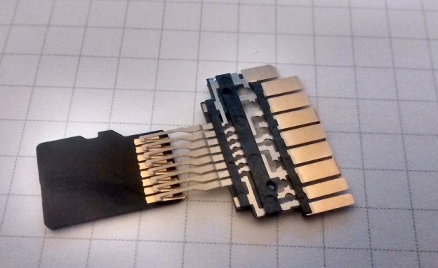
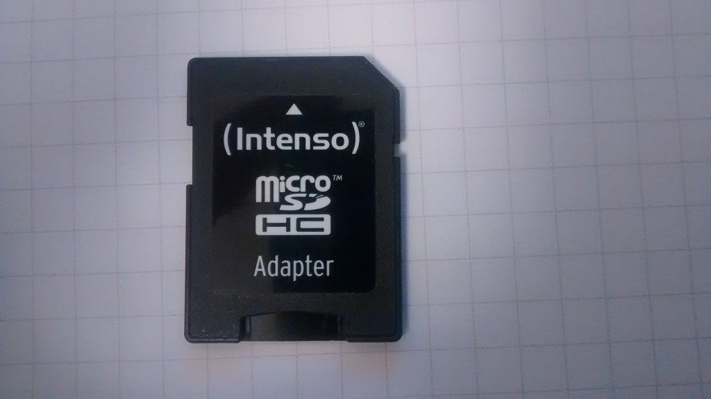
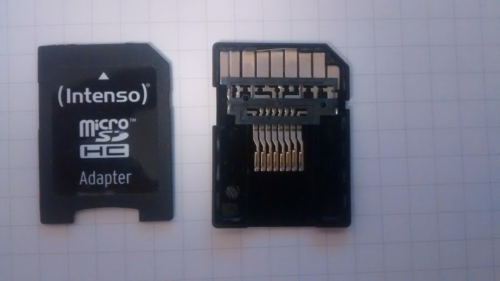
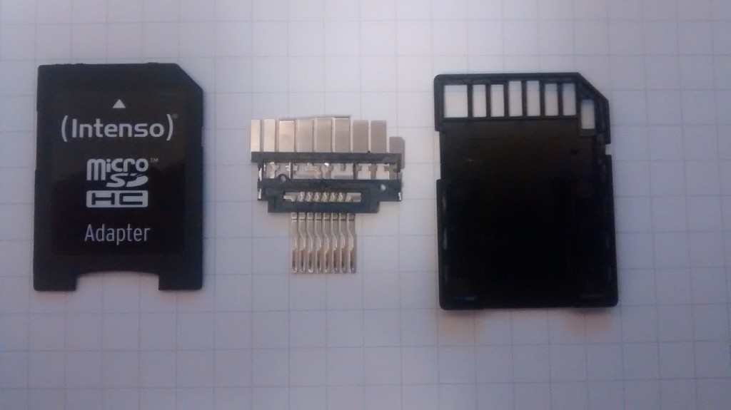
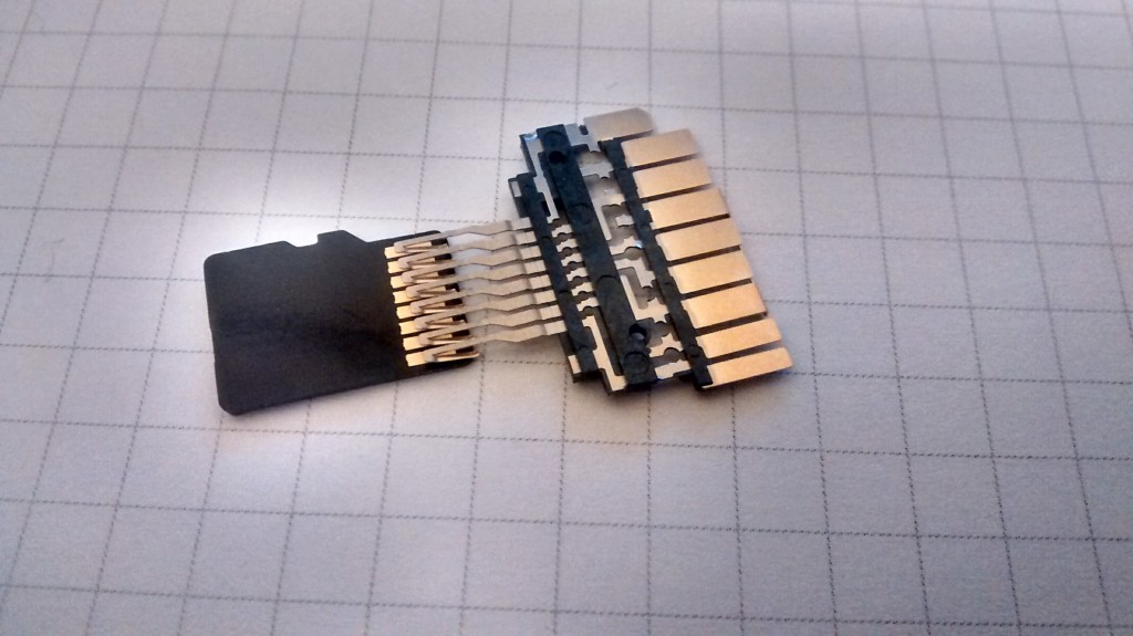
Hi all! Yesterday I was at home and I’ve got on the table a MicroSD adapter. I know, and also imagine, that this kind of adapters are just a contact extension to fit the MicroSD contacts in the SD format. But I need to ‘confirm’ it, so I take the screwdriver to open it, and here’s the result:

MicroSD Adapter TeardownThis is the adapter that I’ll open and it never will be the same. Once is open, carefully for not break any part, I obtain the three parts that make up the adapter: two plastic covers and the contact extender.

MicroSD Adapter TeardownThe extender can be removed carefully from the back plastic, and has enough quality for this kind of piecesThe extender can be removed carefully from the back plastic, and has enough quality for this kind of pieces:

MicroSD Adapter TeardownOn the MicroSD part, the contacts are folded, and acts like a spring when the microSD is inserted on the adapter:

MicroSD Adapter TeardownWith this my curiosity is satisfied, at least until I find more things to open 😉

  • Twitter
  • del.icio.us
  • Digg
  • Facebook
  • Technorati
  • Reddit
  • Yahoo Buzz
  • StumbleUpon
Portable temperature, humidity and light ambient datalogger

Portable temperature, humidity and light ambient datalogger

UPDATE: Here’ the BOM file, I forget upload it: BOM_PIC_DATALOG_V1.0_WEB

UPDATE: Also in Adafruit’s blog. Thanks!

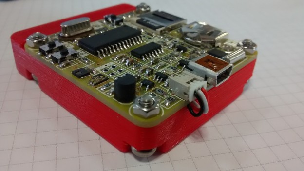
Hi all! I’m continuing here with the last board I design and now I’m continuing testing. It’s a battery-powered small datalogger based on a PIC18F2620 microcontroller. The idea comes a few months ago, talking with a friend. He needs something to  monitoring temperature and humidity inside a sea container, for a three weeks travel from Spain to China. Low consumption is important, in order to have maximum autonomy with a small battery. I use a HDC1050 temperature and humidity sensor, and a TEMT6000X01 ambient light sensor. The collected data is stored on a micro SD card. Also the board has a RTC for timestamp, a Li-Ion battery charger, user pushbuttons and leds, and a MCP2221 USB bridge to communicate with the board and configure some parameters through software. Let’s see the board in detail!

Continue reading

  • Twitter
  • del.icio.us
  • Digg
  • Facebook
  • Technorati
  • Reddit
  • Yahoo Buzz
  • StumbleUpon
insolito

Insolito: Control Your Life With Your Shoes

UPDATE: Insolito project is again available on Indiegogo so it’s time to support this grat project! You can check all the info here and, of course, any question or suggestion are welcome.

Hi all! A few days ago, start on Indiegogo a new campaign where I’m involved in the last months, the Insolito project. Thanks to Sa’ed Qariab, CEO & Founder of The Walking Tech company, I can participate in this project, designing and manufacturing the first units of this intelligent insoles.

Insolito: a smart insole that enables fitness tracking, app shortcuts and emergency alarms with every movement.
Insolito, by The Walking Tech, was launched earlier today on Indiegogo. The new hardware start-up, The Walking Tech, claims that Insolito is the ultimate wearable that is yet to be invented, as this insole is embedded with a smart system that enables its user to control their lives through foot taps.
Insolito is a comfortable and padded insole that can be inserted into any type of shoes. Once activated, the smart system can be controlled through a phone app that works on iOS and Android phones.
The smart insole is fully equipped with fitness tracking functions. It detects movement and counts the number of steps you walk, distance and speed of walking/running. Moreover, it keeps count of the calories that you burn all through the special circuit and sensors inside the insole.

insolito

Better still, Insolito enables you to create app shortcuts through customized foot tap patterns. With Insolito, you can take a selfie, make a call, and open any app with a foot tap. This feature is especially useful for taking photos with your hands free.

insolito

In addition to all that, Insolito introduces a special SOS feature that saves you out in emergencies, especially when you cannot reach your phone. In any case of emergency, a special foot tap pattern will activate Insolito to call 911, send a message and your location to your family and friends, and even post to social media for you:

insolito

This special insole comes with a wireless charging pad, and with a 30-day long battery. It can be fully charged under one hour.

You can pre-order Insolito today through Indiegogo, with a price starting from $69, and with the worldwide delivery expected to commence in December 2016.

The team behind this product is The Walking Tech, a group of young engineers from Palestine who have been working on fitness devices and wearables for three years.

Insolito Features and Facts:

  • Fitness tracking: counts steps, distance, speed and calories
  • App shortcuts: enables the user to run any app, take photos or make calls through foot taps
  • SOS feature: through a special foot tap, it calls 911, sends messages and posts to social media for you
  • Wireless charging: Insolito comes with a wireless charging pad and charges in less than an hour
  • Battery: Lasts for one full month
  • Price: Early bird starting from $69


  • Twitter
  • del.icio.us
  • Digg
  • Facebook
  • Technorati
  • Reddit
  • Yahoo Buzz
  • StumbleUpon
Dual USB Converter

Dual USB Serial and I2C Converter

UPDATE: Some places where the project appears. Thanks to all!!

Hi all! After a couple of months with a lot of work, I come here again with the last board I develop before Christmas. It’s a dual USB serial and I2C converter based on two MCP2221 Microchip 2.0 USB-Serial bridges. I develop it as a need on my work with the last project I’m involved. I need to monitor a serial communication between two devices. With only one converter, I must choose between RX and TX lines to monitoring the traffic. With this solution, I can listen at the same time TX and RX lines, so the monitoring is more easy. And with a software like Docklight (you can download a free evaluation copy here), you can choose the monitoring option to display both channels. After the break you can find all the technical info of the board!

Continue reading

  • Twitter
  • del.icio.us
  • Digg
  • Facebook
  • Technorati
  • Reddit
  • Yahoo Buzz
  • StumbleUpon