I develop this MCP23017 Breakout Board to interface a 2×16 LCD display with any microcontroller using a standard I2C bus. Typical 2×16 displays needs at least 6 lines to work (when working in 4-byte mode); in some cases, this will be prohibited for some microcontrollers. With this board, you can control it with only two lines (I2C bus) and, by the same price, obtain a few more IO’s. I use the MCP23017 I2C expander as a bridge. This integrated circuit provides 16 IO’s over a standard I2C bus. All the pins can configure as inputs or outputs independently, and supports high speed I2C (up to 1,7MHz). Also, this device has three hardware address pins that allow connecting up to 8 devices in the same bus. The rest of the features can be seen in the datasheet.
UPDATE: Dominic Amann shared this board on OSH Park, you can order here: https://oshpark.com/shared_projects/KNHdhwLN
- The hardware
The scheme of the board can be downloaded here. In the fist page, there’s the input and output connectors, two LC filters for power supply, a green led to indicate that the board is power and the blocks corresponding to the expander and the LCD connector. Also, you can see R1 and R2, this resistors are the pull-up for the I2C bus. If the bus where you connect it doesn’t have these resistors, you can populated here (1K5 – 4K are admisible values). If the bus already has this resistors (such is my case) then you don’t need to populate it. In the second page, there’s the scheme of the MCP23017 expander. About this page, some tips. Reset pin is at high level (I don’t use it), so the device is always working. Also, the INTA and INTB interrupts are not used, so these pins are not connected. The address direction of the device is configurable by three jumpers in the scheme. With this, you can connect up to eight expanders in the same bus (more about this soon…). In the PCB, I use 0 ohms resistors to configure the address. Port GPA is used as the data bus to the display. Two signals of the GPB port are used to control signals to the LCD, and three more signals (GPB2 – GPB4) are connected to a three general purpose leds that will be usefull in the debug stage. Also, both ports are connected to a general connectors in order to use it as general IO’s if you don’t want to control the LCD. Also, I include an external EEPROM over the same bus. I use the 24LC256 from Microchip, that has a capacity of 32 KBytes. This memory has also three pins to configure the address, so with the same address configuration of the expander, you can configure it, and again you can put up to 8 of these memories in the same bus. At the end, in the last page of the schematic, there’re the two connectors for the GPA and GPB ports, and a stage to control the backlight of the display, if you populated a model that has this feature. This part of the circuit is based on a PNP transistor (BC856) controlled by the GPB5 output of the expander. As I don’t use it, I don’t populate it, not the resistors asociated (R7 – R9).
- The board
I send the board to seedstudio. I make a panel of two units of this board, with a total dimension of 48×49.5 mm. Each board has a dimension of 48x24mm, so I can fit two of them in less than 50x50mm board. The quality of the boards is very high, at this time all I mounted works fine. The only disavantage of this is that you must separate the boards without any kind of help like scoring, holes, etc. But with some patience and a small saw, I can obtain my individual boards!!! Here you can download the gerber of the panel. If anyone wants the PCB project or the single board gerbers, please contact me.
 Two boards per panel, ready to cut it!!

Top Layer

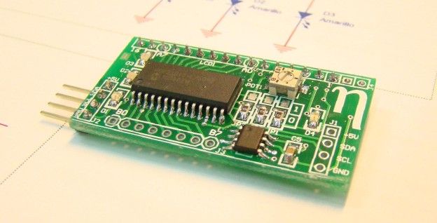
Components mounted on Top Layer (hand-mounted)

Bottom Layer

Components mounted on Bottom Layer (hand-mounted)
 Board fully assembled and mounted over the 2×16 LCD
- The software
I just develop a small software to test the board works. It’s developed for an AT89C51RE2 microcontroller (DSETA CPU, coming soon). It’s write in C languaje under Keil C51 compiler. There’re three main files:
- I2C_EXT.c – File that has the I2C funtions. These functions implement a bit-banged I2c, using two general purpose pins. Basic functions for I2C communications are implemented:
123456789void I2C_EXT_delay (unsigned char t_delay);void I2C_EXT_Start (void);void I2C_EXT_Stop (void);void I2C_EXT_txACK (void);void I2C_EXT_txNACK (void);void I2C_EXT_Write (unsigned char OUT_DATA);unsigned char I2C_EXT_Read (void); - MCP23017.c – File that has the functions to communicate with the MCP23017 over the I2C bus previously implemented. It only has two functions: one for initialize the driver and other to send a value to an output port:
12void Inicializa_MCP23017 (void);unsigned char MCP23017_Enviar_Dato (unsigned char puerto, unsigned char dato);
- LCD_2X16_I2C.c – File that has the functions to communicate with theLCD in 8 bit mode. It has the classic functions to initialize it, send a command or a data, or print a line:
12345void LCD_delay_I2C (unsigned int t_delay);void LCD_cmd_I2C (unsigned char comando);void LCD_dato_I2C (unsigned char dato);void LCD_init_I2C (void);void LCD_print_I2C (unsigned char *cadena, unsigned char linea);
Here you can download these files with the implementation of all the functions: MCP23017_Files
And finally, a couple of inages of the board in action:

MCP23017 breakout board connected to the CPU

Display shows the system status, date, time and temperature!


hey
I really like your post of ” interface 8 LCD displays and 24 leds with only two wires”
i want to ask that if i do it in arduino board or any stamp board (Atmega 16 or PIC) ,then can we control 8 LCD display and 24 led with two wires using I2C.
Yes, of course. You only need an I2C bus and power supply (+5V) to connect to the MCP23017. With this configuration, you can manage up to 128 IO’s (16 IOs in each MCP23017). The I2C bus can be hardware or, like in my example, can be implemented by software. In the code of this project you can find the functions in C to implement a I2C software bus. For reference, you can visit the Keil C compiler I2c sample programs: http://www.keil.com/i2c/examples.asp. I hope this info will useful for you!! Regards, Jesus
Pingback: DSETA board, a CPU based on the Atmel AT89C51RE2 | Designing Electronics in Spain
Pingback: MCP23017 Brekout Board | Make, Electronics projects, electronic Circuits, DIY projects, Microcontroller Projects - makeelectronic.com
Can you send me a link to the gerbers for a single board please? I would like to use this for the project on my website link.
I would really like to use your circuit in a project I am building.
I can use either single or double, but I can’t use the gerbers without a “board outline” file. Is there a GKO file? oshpark seem to require one.
Hi Dominic!
I just come home, in the next days I’ll send you the necessary files to manufacture the board, including the GKO file (outline board shape) and the drills, don’t worry about it! Give me a couple of days to review and modify the files and I’ll send you!
Thanks again for your interest in the board and for read the blog!
Best regards, Jesus
Oh – and drills would also be required.
I have discovered that your .TXT file is a drills file. However, in my layout software, it comes out misplaced, and at a different scale to the other (excellent) files. I am greatly lacking in expertise in manipulating pcb layout software. I suspect that this could be easily corrected by someone with the expertise. I also suspect that the outline file could be deduced/inferred somehow.
Is there anyone out there who could perhaps point me in the right direction? I feel that this is so close yet…
Thanks for the files, they worked flawlessly. I will probably be picking them up tomorrow at work. I assume I can leave the 24LC256 out of the board if I have no use for it?
The board is now available on Osh Park as a shared design.
I am driving the board from a Raspberry Pi.
Yes of course, if you don’t need it, you can left unpopulated. Also, keep in mind the config of the JP1-JP3 resistors to set the address of the MCP23017. Happy debugging, and any question you have, please tell me!!
I really like this board and would like to populate it but I am new to smd components… I ordered and 805 set but they seem pretty small. If you guys have a components list to popolate the board or point me in the right direction it would be much appreciated.
Hi Ray! Thanks for read the blog and your interest in the board! 0805 components only need practuse to populate by hand. For only one-two prototypes, professional mounters will be very expensive. So, you can try to mount it yourself or, if you want, I can help you to mount it. If you’re interested, send me an email and we can discuss it.
Best Regards, Jesus
Gracias por tu projecto, esto me hace mucha falta para un “virtual flight simulator cockpit” que estoy construyendo.
?Me puedes mandar el esquema y el PCB project?. Muy agradecido,
Arturo