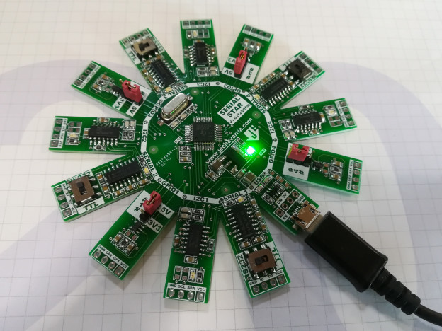
Hi all! Here’s one of the last board I design the last year. On 2016, I develop the Dual USB Serial and I2C Converter board. Although this board works fine, it has a couple of lacks. First one, is that to use the both converters, you need two free USB ports. Is a minor problem today with USB hubs, but you need the hub and also two USB wires. And the other problem is that this board uses mini-USB connectors. Of course today you can still find it, but aren’t as common as the micro-USB wires. For this two reasons, I decide to upgrade the board, add the micro – USB connector and put a USB hub inside it. Because I choose a 4-port USB hub, I use also 4 USB serial converters. With some addons, you can select power supply value (5V, 3V3), serial levels (TTL, RS232) and GPIO functions in an independent way for each converter. So, let’s see how works this USB Serial Star, a 4 in 1 USB to Serial and I2C Converter.
- THE HARDWARE
This board is basically a 4-port USB hub with 4 USB to Serial and I2C bridges and some addons. The USB hub is the TUSB2046I, from Texas Instruments. The USB Serial bridges are the MCP2221A from Microchip, the same reference I use on the past. First of all. the schematic of the board, you can download here: EEL_SERIAL_STAR_V1.0. The schematic is simple, here’s a brief description of each page:
- Page 1: Main diagram. Interconnection of all the blocks of the scheme. Here’s the micro – USB connector, and also a 2.54mm header connector with the USB signals. This is reserved for use with a soldering cable or in the case the hand soldering of the micro – USB connector fails.
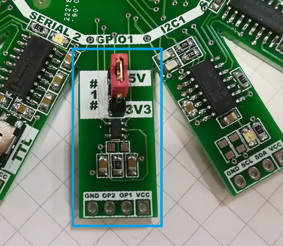
- Page 2: Power supply. The board is powered via USB, so input power supply is +5V from the USB port. There’s a LDO (U1) that allows 3.3V onboard. With the jumpers S1 – S4 you can choose the voltage of each USB serial converter, between 5V from USB or 3.3V from the LDO. Ater the jumper, before powering the USB serial converter, there’s a single channel current limited power switch, the TPS2041B. The idea is use this switch to detect overcurrents on any of the four USB serial conveters and disconnect it, allowing the rest of the ports working without problems. For each switch, there’s a not-assembly resistor, to use it in the case you want to bypass this switch.
- Page 3: USB Hub. Based on the TUSB2046B from Texas Instruments, is a 4-port USB 2.0 12-Mbps USB full-speed hub. It provides one upstream port and four downstream ports in compliance with the Universal Serial Bus (USB) specification as a full-speed hub. For the upstream port I used a transient suppressor, the SN65220, also from Texas. The configuration of the TUSB2046B is the following one:
- Pin BUSPWR = 0 –> Self powered mode
- Pin EXTMEM = 1 –> External EEPROM interface disabled
- Pin EEDATA/GANGED = 0 –> Per port power over current detection
- Pin TSTPLL = 0 –> Normal 6 MHz operation
- Pin TSTMODE = 0 –> Normal 6MHz operation
- Clock generatio: External cristal, 6MHz.
- Pages 4-7: USB Serial conveter. Based on the MCP2221A from Microchip, is a USB 2.0 to I2C/UART protocol converter with GPIO. The setup is the same for the four converters, so all the features are the same, independient of the used converter. Power voltage of every USB serial converter is independient and configurable between 5V or 3.3V. Because the output levels of the MCP2221 goes with the power voltage, you can have a serial (or I2C) levels of 5V or 3.3V just moving a jumper. The associated connectors for each USB serial converter are the following ones:
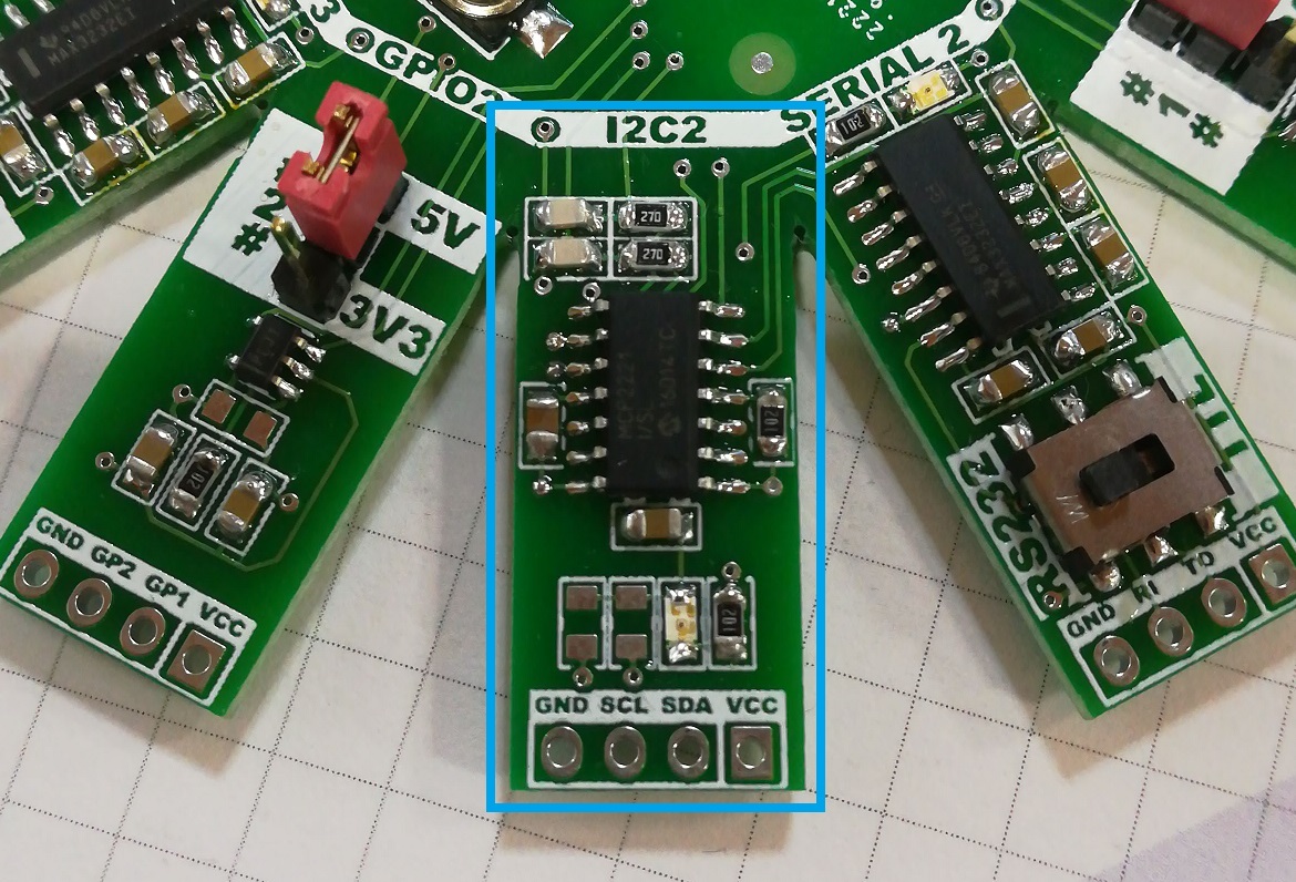
- I2C connector (J2, J5, J8, J11): 4-pin 2,54mm header with VCC, GND and I2C lines. These lines has 5V or 3.3V, it depends of the position of the power jumper. Also, for monitoring I2C communications there’s a yellow led to indicate I2C activity. This is the default function for the GP3 pin.
- GPIO connector (J4, J7, J10, J13): 4-pin 2,54mm header with VCC, GND and two general purpose GPIO lines. Like I2C signals, these lines has 5V or 3.3V, it depends of the position of the power jumper. The function of these pines are configurable via PC application from Microchip, and has the following options:
- GP1: Clock Reference Out / ADC Channel 1 / UART TX Led / External Interrupt Edge Detector.
- GP2: USB Configure Status / ADC Channel 2 / DAC Output 1

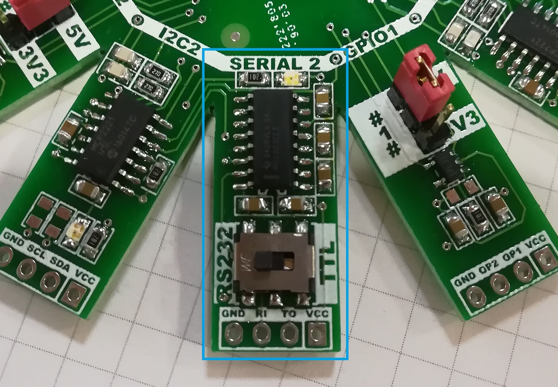
- Serial connector (J3, J6, J9, J12): 4-pin 2,54mm header with VCC, GND and serial UART lines TX and RX. Each USB serial converter includes a TTL – RS232 transceiver, the well known MAX3232, and a slide switch, WS-SLSV from Wüth. Also I use the GP0 pin to connect a red led, that indicaters there’s a RX activity on the serial port. With this setup you can choose the output serial signals between:
- Serial TTL 5V: Select power jumper on 5V position and serial switch on TTL position.
- Serial TTL 3V3: Select power jumper on 3V3 position and serial switch on TTL position.
- Serial RS-232 level: Select serial switch on RS232 position. Power jumper is independient on this mode because the MAX3232 can work with 3.3V or 5V inputs.
- PCB DESIGN
Every USB serial converter needs 3 4-pin header connector, so this means a total of 12 connectors. Also I need one more for the micro-USB connector. For this reason, I think it was a good idea design the board as a star with 13 points.

As you can see, the point for the micro-USB is shorter than the rest, just because you need to plug the wire and I dont want to take too much space. For the three connectors of each MCP221, I follow the same order: the three connectors are one near the other and, from left to right, are: Serial – I2C – GPIO. The spacing and disposition is the same for the four converters. In fact, I do all the placement and routing for the first USB converter and when it was finish, I just copy and paste the block with an angle of 27.69º (360º / 13 points). Updating the references acording to the schematic, the four blocks are ready routed!
This time I send the Gerber Files to JLCPCB, is the first time I use the service, I like to test different manufacturers. The resume of the fabrication is:
- 10 PCB’s : 1,76eur / Shipping to Spain: 8.25 eur –> Total Price: 10.01 eur
- Process time: Just 24 hours from receive the Gerber files to package the boards and ready for shipping:
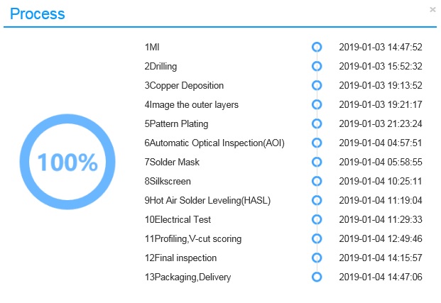
- Delivery time: 18 days
Quality is really good for the price, like in most of this PCB companies. Positive points are total price and process time. On the negative side, choosing a different green color for solder mask increases the cost of the boards. Noting important, really.
- SOFTWARE
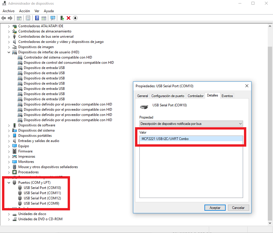
Once the board is assembled, is time to test it. First of all you need the MCP2221 driver, on the Microchip webpage there’s the driver link for Windows, and driver information for Linux and MAC. I do all the following test under Windows 10 Pro x64. When you plug the board on the PC, power green led turns on and enumeration starts , you can see the four USB serial ports available:
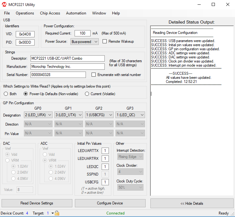
Microchip also provides two interesting tools to work with the MCP2221 USB converter. The first one is the MCP2221 Utility (v1.0.1). This tool allows you to configure each parameter of each USB converter: USB identifiers, power configuration, descriptor,GP pin configurations, password protection…..Is a really nice tool for customize each MCP2221:
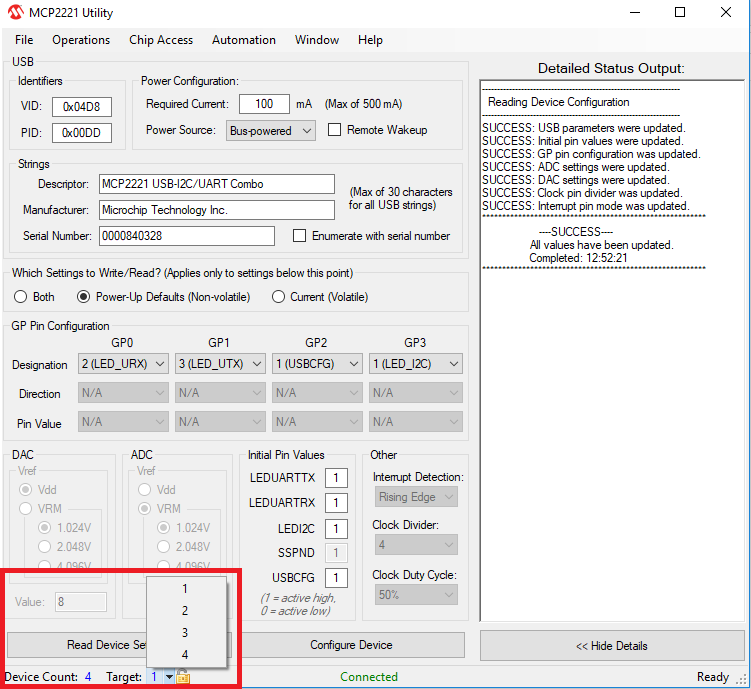
On the bottom left part of the application you can see the connected devices, 4 with actual setup. Doing click on the arrow near the target label you can select the device you want to configure:
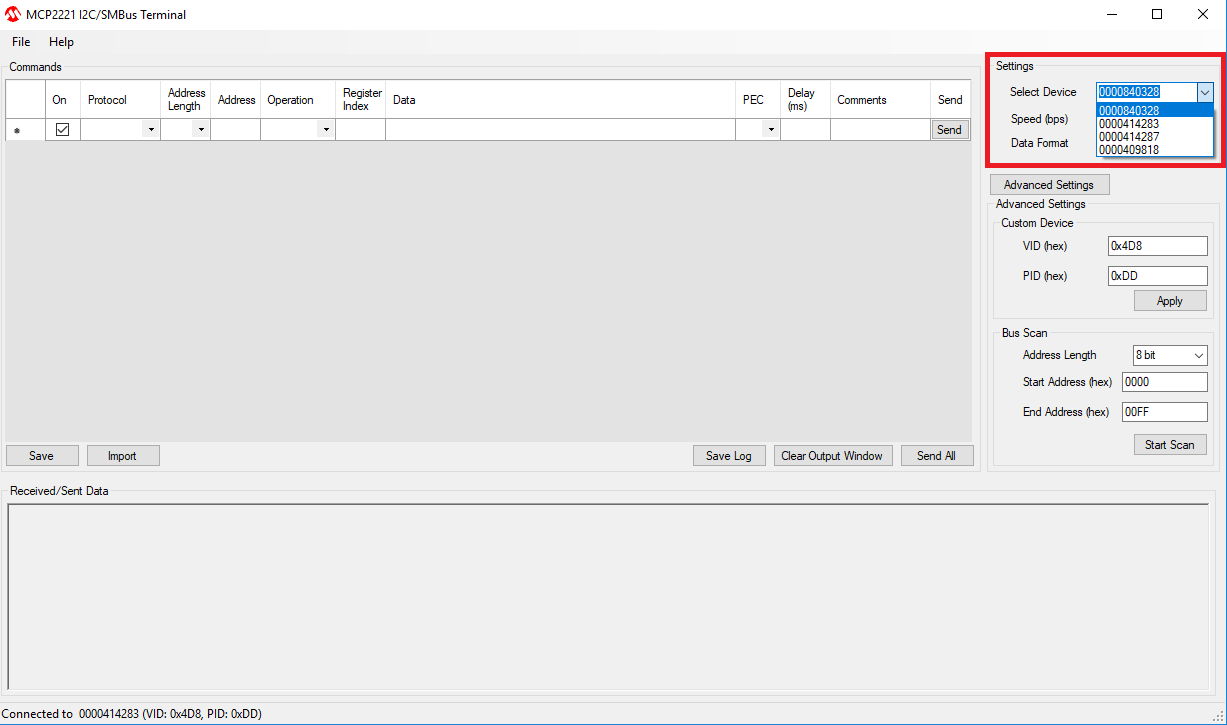
The other nice tool from Microchip is the MCP2221 I2C/SMBus Terminal (v2.0). This tool allows you to manage the I2C bus on the USB converter. Of course you can choose one of the four MCP2221 attached, on the top right part of the application:
You can send or receive commands to an I2C device attached, and also can do a bus scan on the address range you specify. For a rapid test, I connect a 128×64 OLED display to the USB converter #1 and perform a scan bus from 0x00 to 0xFF address: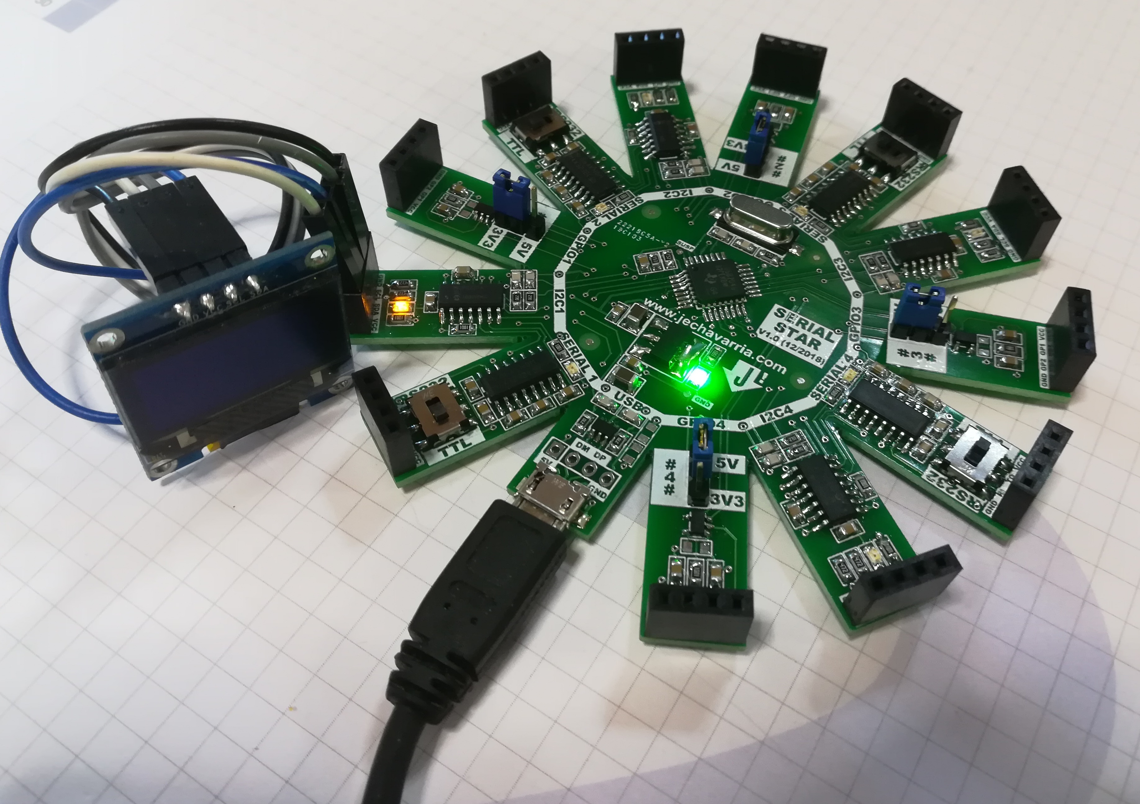
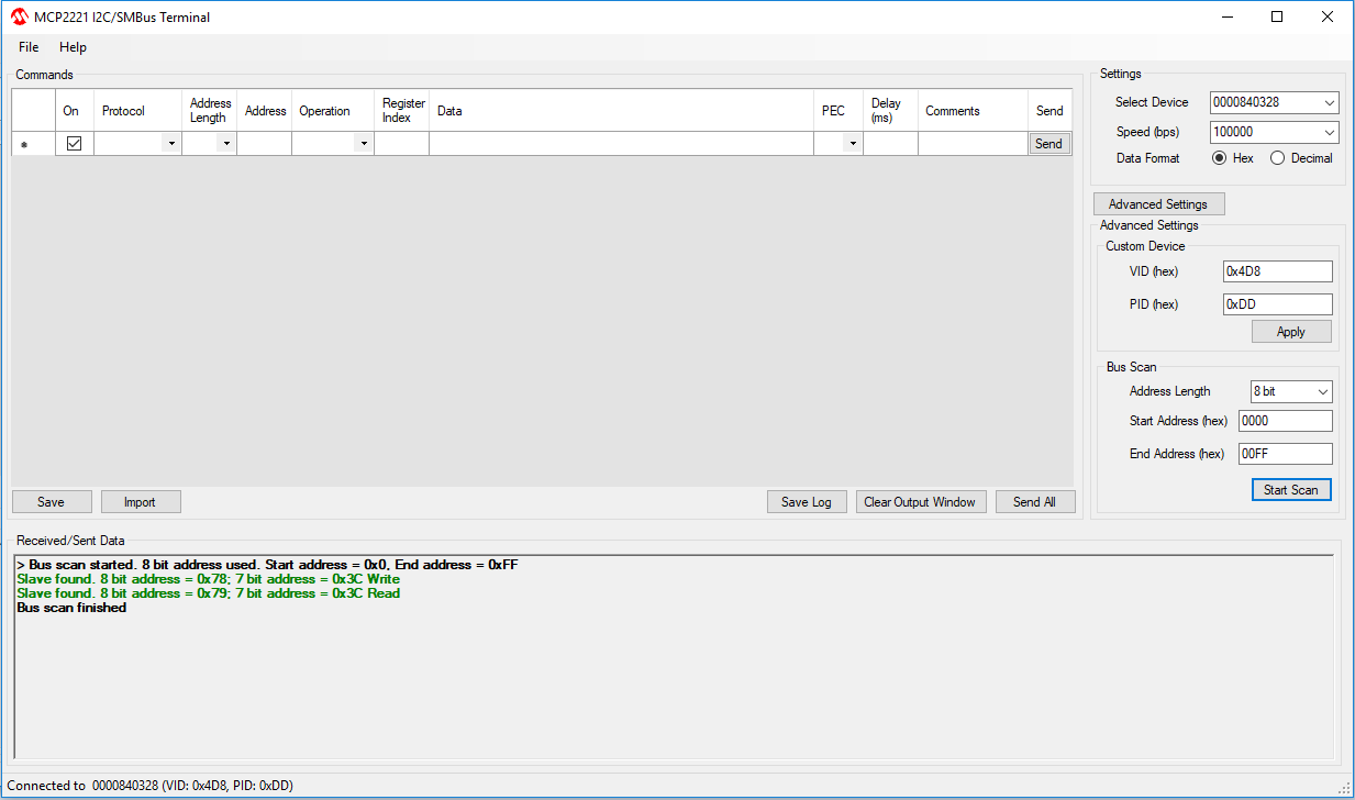 You can see that scan finds a slave device on the address 0x78 / 0x79 (8-bit I2C address).
- SERIAL TEST AND SMALL ISSUE
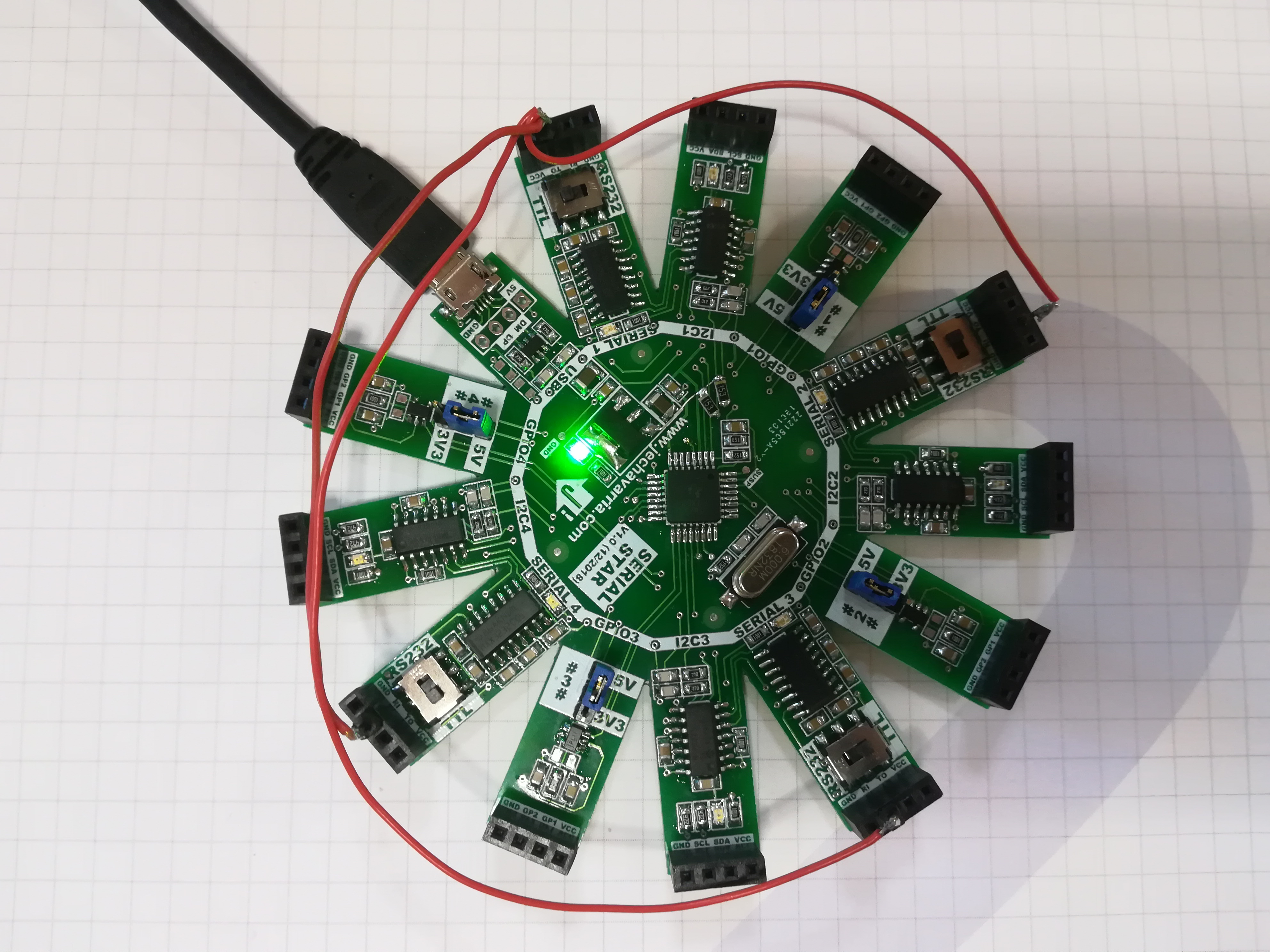
After checking the I2C features, is time to check the serial communications. First test is open 4 terminal Windows (with Tera Term Pro, for example), use one serial port as transmitter (COM15) and the rest as receiver (COM11, COM12 and COM14), and check if all goes fine. Here’s the setup I use, really simple:

First test did not work as I expect, I send data but I don’t receive the correct characters. After some investigation, reviewing the schemes finally I notice where’s the problem. Is focused on the TTL – RS232 switch selector. There’s an error on the selection lines; if you put the switch on the TTL position, you transmit with TTL levels but RX line expect receive RS232 levels. And also if you use the RS232 position, you transmit on RS232 levels but RX line expect TTL levels. So, on this first test, I need to configure transmitter port as RS232 and the rest of receive ports as TTL (because on this position they expect RS232 levels also). With this setup there’s no problem and communications goes as expected:
Also you can see the red leds on the board blinking every time a new character is received:
So, I think is time to develop the 1.1 version of this board to fix this 😉


This post is also available in: Spanish
Pingback: Serial Star, a 4 in 1 USB serial and I2C converter – gStore
Pingback: Serial Star, a 4 in 1 USB Serial and I2C Converter - Electronics-Lab
Pingback: Four Independent USB to Serial/I2C/GPIO Converters on a Single PCB | iotosphere - Internet of Things
Pingback: Serial Star, a 4 in 1 USB Serial and I2C Converter - ATMega32 AVR