Hi all! Here’s the new project where I’m working a couple of days. Since I develop the SIM900 module and test it, I don’t work with it. Also, I’ve got at home some samples of the MCP2200 USB bridge that I want to test it. So make an USB interface for this board was the perfect idea! This allows to use the SIM900 board with a PC, Raspberry or similar, with the plus of no need external power supply or control signals. Just plug the USB cable on the board and start communicating with the world!
- The Hardware
To develop this board, again I use element’s I’ve got at home. First of all, the scheme, that you can download here: SIM900_USB_CONTROLLER. This is the USB interface, you may also want the scheme of the SIM900 module, to have a global vision of both boards. All the info of this module is here.
The scheme shows the required hardware for the USB interface. It’s really simple, and has the following parts:
- USB connector: Type B, right angle. The easiest connector to solder in the breadboard.
- 5V / 3V3 LDO: The SIM900 interface works with 3V3 levels, so the USB brigde must comply with this. For this reason, I include the MC33269 LDO, so with the 5V from the USB port I can power all the USB stage with 3V3. Note that the internal reference VUSB pin on the MCP2200 is connected to this 3V3 power supply. With this configuration, the internal LDO of the MCP2200 is disabled. Also, another consequence is that the ‘1’ logical level on the GPIO pins will be at the 3.3V level.
- MCP2200 Usb bridge: An easy way to have a bridge between USB and a serial port. This chip is a 18F14K50 PIC micrcontroller with a custom firmware, you can read here about it. I’ve got a couple of samples at home in 20-pin SO format, so with the help of an adapter like this one, it’s very easy to include in any design. Also, people at Dangerous Prototypes develop a breakout board that I used as inspiration. About the circuit, nothing special: it requires an external 12MHz crystal and a pull-up resistor in the pin 4 (RST). I also use pins 5 and 6 to signaling the activity on the serial port with two led’s. It’s really easy to use.
- SIM900 Board connection: The interface with the SIM900 board I develop previously. To power this board, I use the 5V from the USB port. And TX / RX signals to control the modem, nothing more.
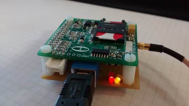
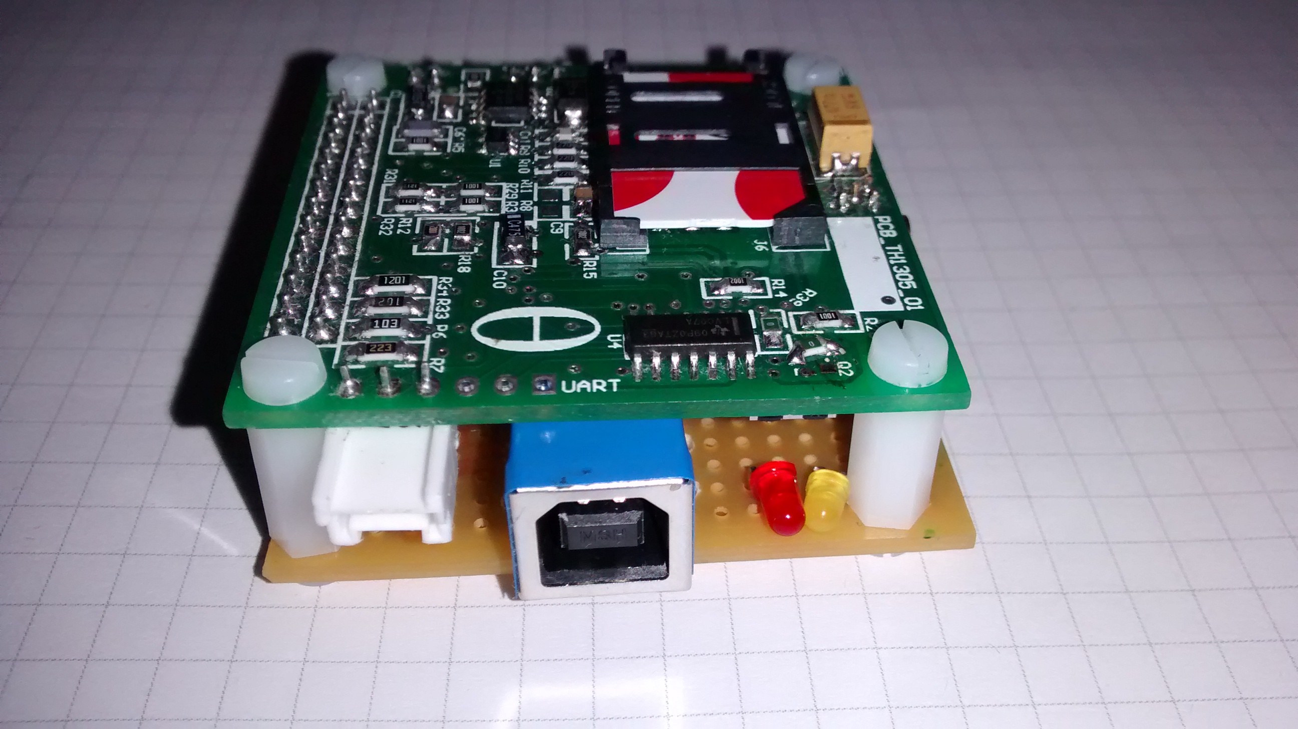
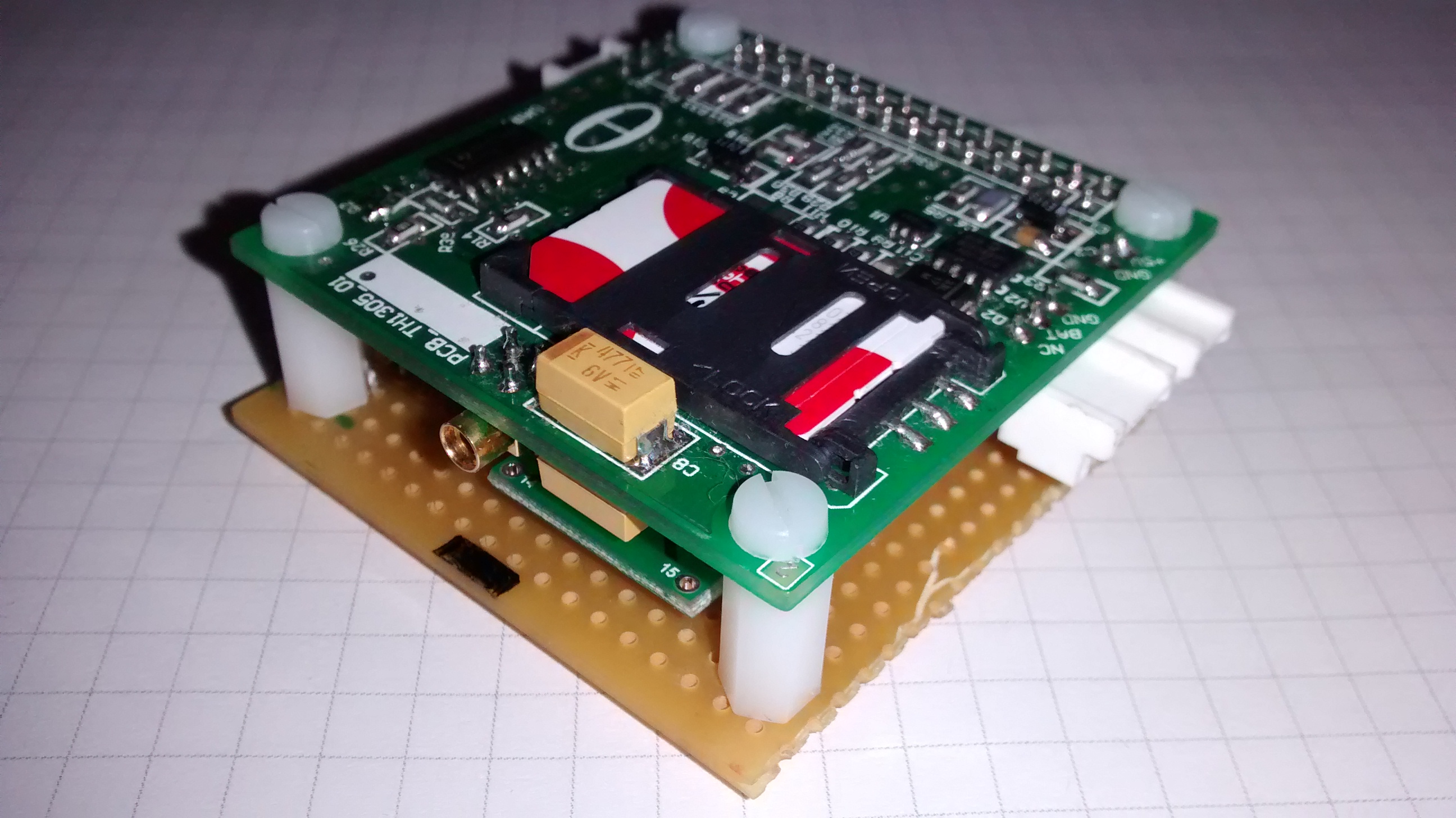
Here’s a couple of photos of the board with the components:
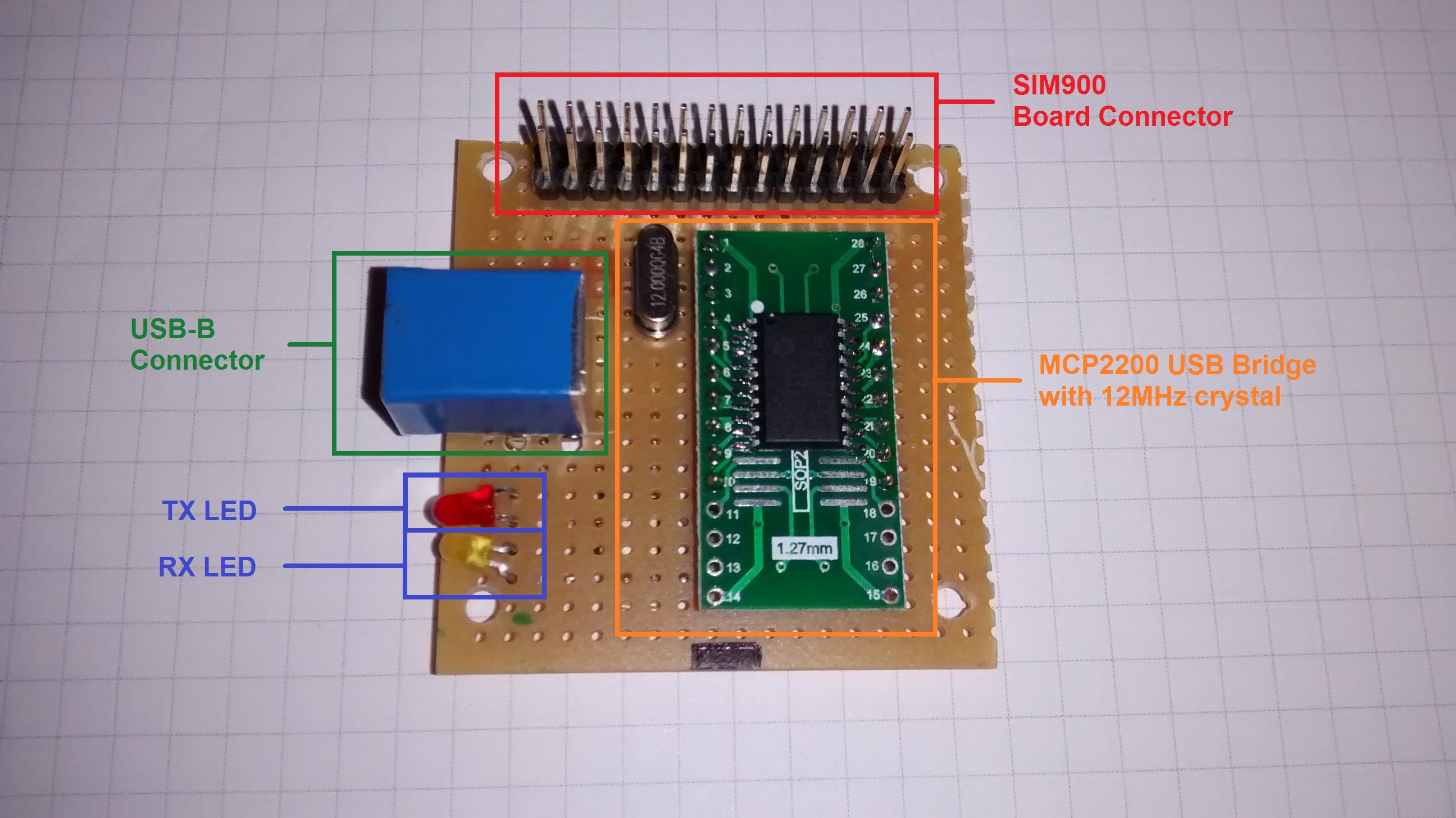
TOP LAYER
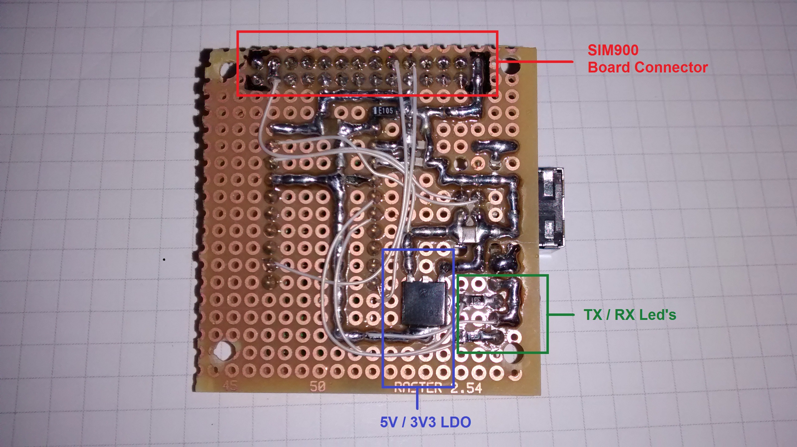
BOTTOM LAYER
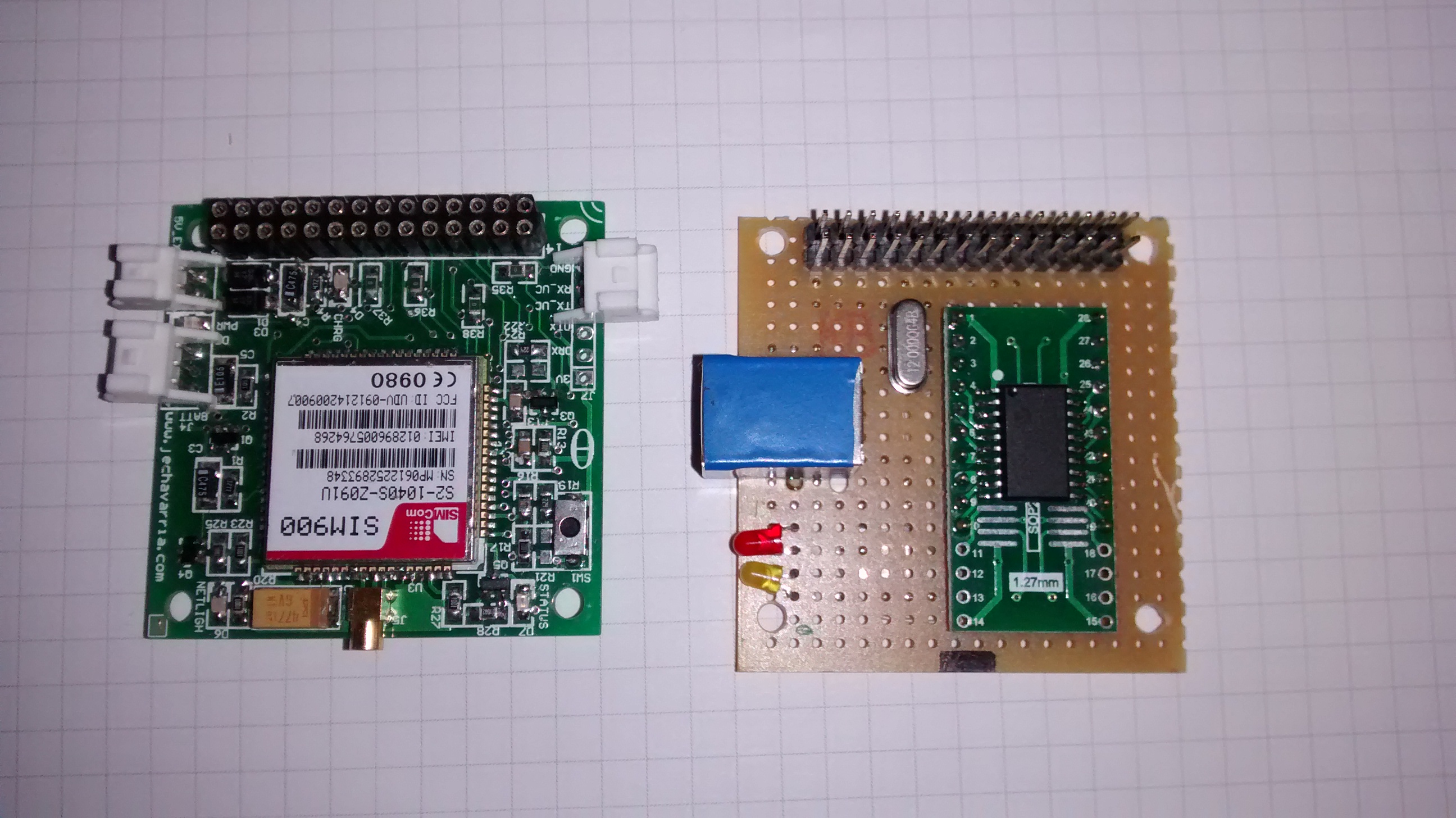
The prototype board has the same dimensions and form factor as the SIM900 board:
 Once I solder all the components and check that the power supply is correct (both 5V and 3V3), it’s time to connect the SIM900 module and check the communications over USB. The first thing to do is install the MCP2200 driver. You can download from the Microchip webpage or, if using Windows, directly from here: MCP2221 Windows Driver 2014-10-09.
I use Tera Term terminal to communicate with the SIM900 module using AT commands. For your reference, here’s the latest AT Command Manual from the SIMCOM manufacturer (version 1.07 at this time). All the tests are satisfactory, and includes making voice calls and sending and receiving SMS messages. With the 2x470uF capacitors assembled on the SIM900 board (C8 and C9, check the SIM900 scheme), you can use the modem only with the USB power, eliminating the need of an external power supply.
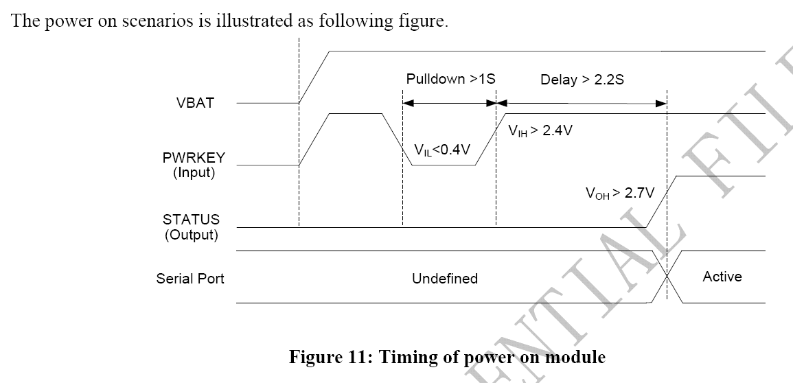
 The only difficult I find in this project is how to power up the SIM900 module when the power supply is applied. This modem requires a low pulse on the PWRKEY input greater than 1 second to power on:
 With an embedded microcontroller this is very easy to implement. Also, the board has a pushbutton to force the power on manually. But this is not operative when you want to control the board with a PC or similar. In this case, you want that when you plug the modem, it powers up immediately, without pressing any button. After some search in the web, I find a solution that seems work: put directly the PWRKEY pin to GND. This allows that SIM900 modem powers up when power supply aplies. I find this solution in a couple of webpages, here’s where I find it in more detail. To do this mod, I remove the Q2 mosfet and put a 0 ohm resistor between the source and drain pins:
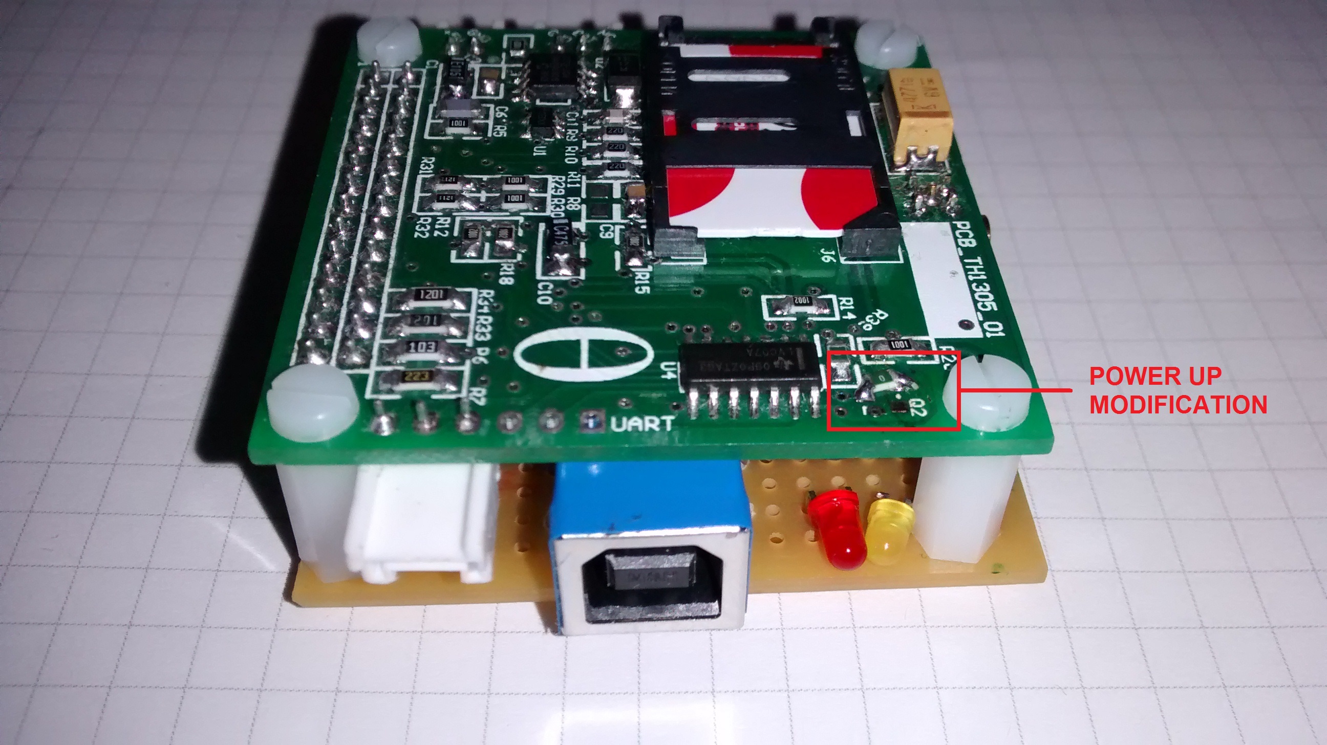
- Configuring the MCP2200
The MCP2200 comes with the firmware ready to use and you don’t do nothing to start working with it. But Microchip offers a small application to configure some parameters of this device, the MCP2200 Configuration Utility. With this utility, you can modify some parameters of the MCP2200, including the Vendor ID and Product ID, default baud rate and functions for the general GPIO’s that are available for the user:
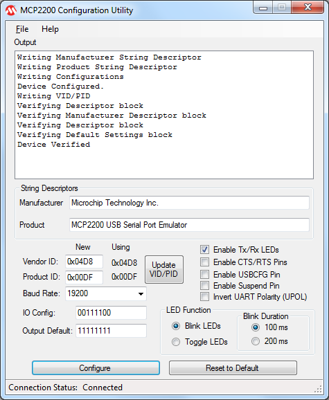
I use it to configure the TX/RX leds. First, check the option ‘Enable Tx/Rx LEDs’. After check it, the rest of the options will be enabled, and you can choose the kind of led function. If you select Blink led, you also can choose the blink duration:


This post is also available in: Spanish