UPDATE: Thanks to Rando, now you can order this PCB on OSH Park. Thanks!!
UPDATE: If you’re interested in mount the board yourself, now you can download the Bill Of Materials (BOM). Happy welding!
Hi all! With a bit of delay, here’s my last work, a PICnano breadboard based on the PIC18F2550 microcontroller. I have in mind a new project and I want to use an small board, like the Arduino Nano board. This new project is battery powered (3,7V Li-Ion battery). After checking the schematics of the Arduino Nano, I see that the microcontroler is powered at 5V. Of course, I can unmount the linear regulator (U3) that is on the board, and bypass the VIN to the microcontroller power supply. But I think it’s funny try to develop a new module when you’ve access to the microcontroller power supply! Also, I want to work with PIC microcontrollers after many years, so here’s what I design!
- The Hardware
The goal of this new design is try to have an Arduino Nano compatible module but with some new features, such have direct access to the power supply microcontroller. First of all, here you can download the schematic of the board: PICNANO BREADBOARD SCHEMATIC V1.0
The board is based on the PIC18F2550 microcontroller, here you can download the datasheet. It’s an 8-bit microcontroller with these features (from the Microchip’s page):
| Program Memory Type | Flash |
| Program Memory (KB) | 32 |
| CPU Speed (MIPS) | 12 |
| RAM Bytes | 2,048 |
| Data EEPROM (bytes) | 256 |
| Digital Communication Peripherals | 1-UART, 1-A/E/USART, 1-SPI, 1-I2C1-MSSP(SPI/I2C) |
| Capture/Compare/PWM Peripherals | 2 CCP |
| Timers | 1 x 8-bit, 3 x 16-bit |
| ADC | 10 ch, 10-bit |
| Comparators | 2 |
| USB (ch, speed, compliance) | 1, FS Device, USB 2.0 |
| Temperature Range (C) | -40 to 85 |
| Operating Voltage Range (V) | 2 to 5.5 |
| Pin Count | 28 |
PIC18F2550 breadboard
These characteristics are enough for many of the small projects I usually do. The two features that are more important for me at this time are:
– It has a full speed 2.0 USB internal module, so you don’t need external transceivers to have a USB interface.
– Power supply starts at 2V, so it’s perfect for a battery powered systems.
The schematic is dividen in functinal blocks:
PIC18F2550 Microcontroller
The main part of the board. It has the basic elements to work with the PIC without external componentes: decoupling capacitors, reset pushbutton, mini-USB connector and external oscillator. And, obviously, the PIC18F2550 microcontroller in 28-pin SOIC package.
Header Connectors
The board has two 15-pin connectors, J1 and J2. The space between pins in each connector is a standard 0.100 inches. The distance between both connectors are 0.600 inches. This allows to use the board in a bread board for fast prototyping. Most of the signals are compatible with the Arduino Nano pinout. Main differences are on pins 13, 14 and 15 of J2. In the PICnano board, in these pins are the VUSB and VCC_EXT power supplies.
Power Supply Selection
The microcontroller of the board can be powered (VCC_UC) from any of these power supply sources:
– From VCC_EXT pin (J2, pin 14). In this case, the microcontroller power supply is the same that you apply on this pin. The limits are the same of the microcontroller operating voltage (2V to 5.5V), and you can use it to power the board from a Li-ion battery dicrectly. BE CAREFULLY when you use this power supply, you acts directly on the microcontroller VDD pins!!
– From an external USB port (VCC_USB).
– From an external VIN power supply (J2, pin 1). The board is ready to mount a linear LDO regulator (NCP1117), like the Arduino Nano board. In this case, the maximum imput voltage is 20V. The NCP1117 has many different output voltages, so you can select the right one according your application (1.5 V, 1.8 V, 2.0 V, 2.5 V, 2.85 V, 3.3 V, 5.0 V).
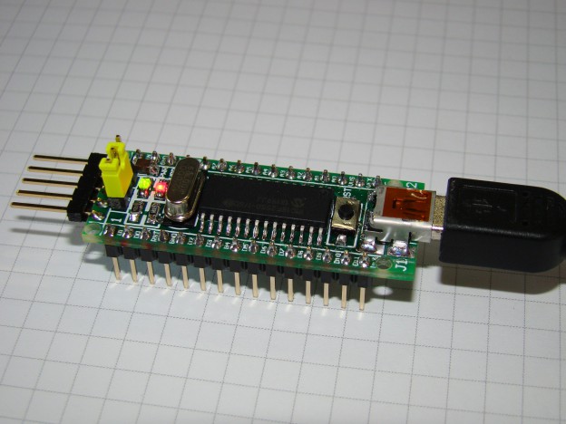
To select the power supply font, you have a jumper on the board (SW2), the yellow one in the image:
PIC18F2550 breadboard
With the jumper in the left position (seeing from the USB connector), the power supply can be from USB or external VIN. On the right position, the power supply is VCC_EXT, directly to the microcontroller power pin.
ICSP Connector
The standard connector from Microchip to program their devices. I use the Pickit3 tool, that also allows debbug the code with the MPLAB environment. This connector is the one you can see behind the jumper.
User Led
A general purpose red led on the UART TxD pin. It’s usefull to start working with the board or for developing the application.
- PCB Design
The board was designed with Altium Designer 13, and you can download the gerber files here: GBR_PICNANO_BREADBOARD_V10. It’s a 4-layer PCB, and the dimensions are 46,5 mm x 18mm. It’s only 3mm longer that the Arduino Nano one. To manufacture the board, I use the DirtyPCB services. I like their board quality on 2-layer boards (see my last project) and I want to test the 4-layer designs. And the result is excelent again:
[metaslider id=1125]
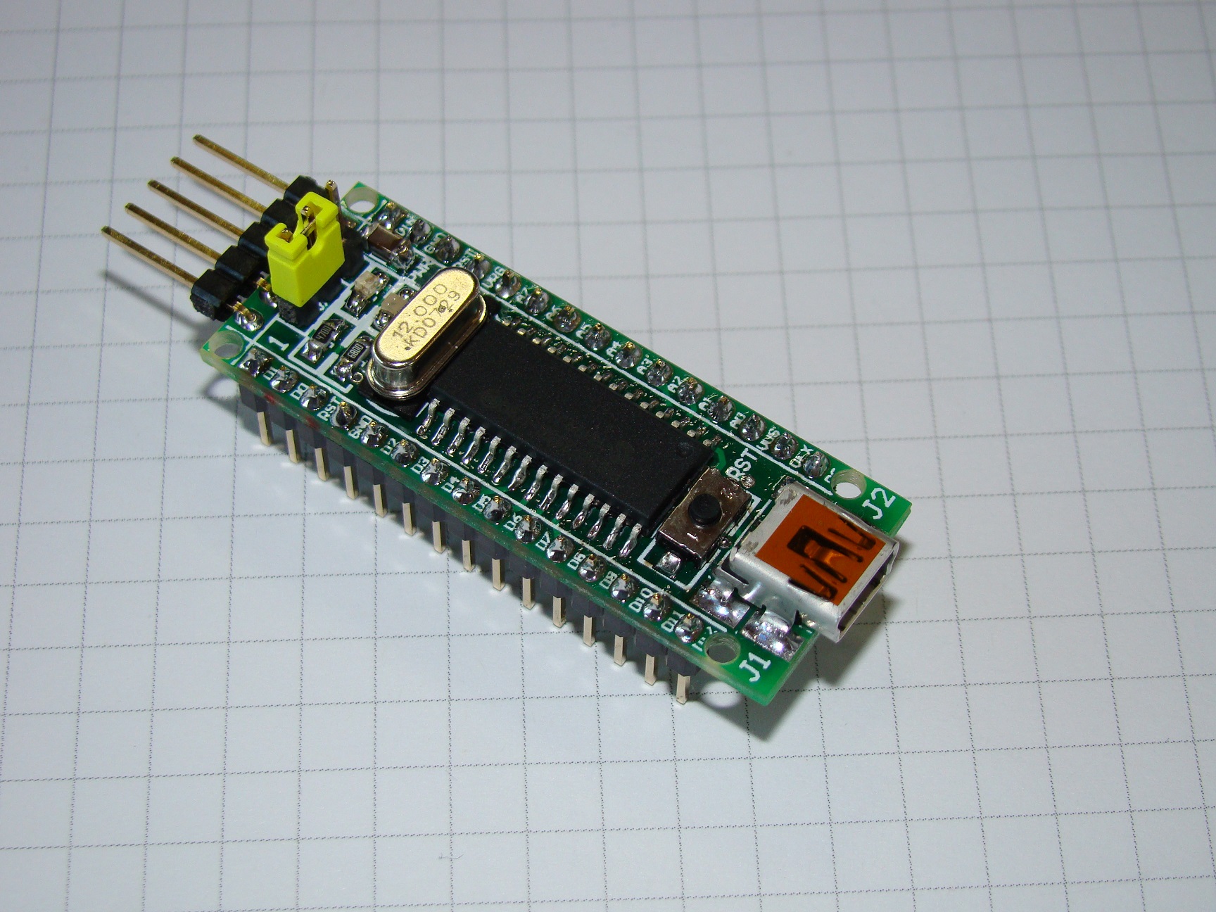
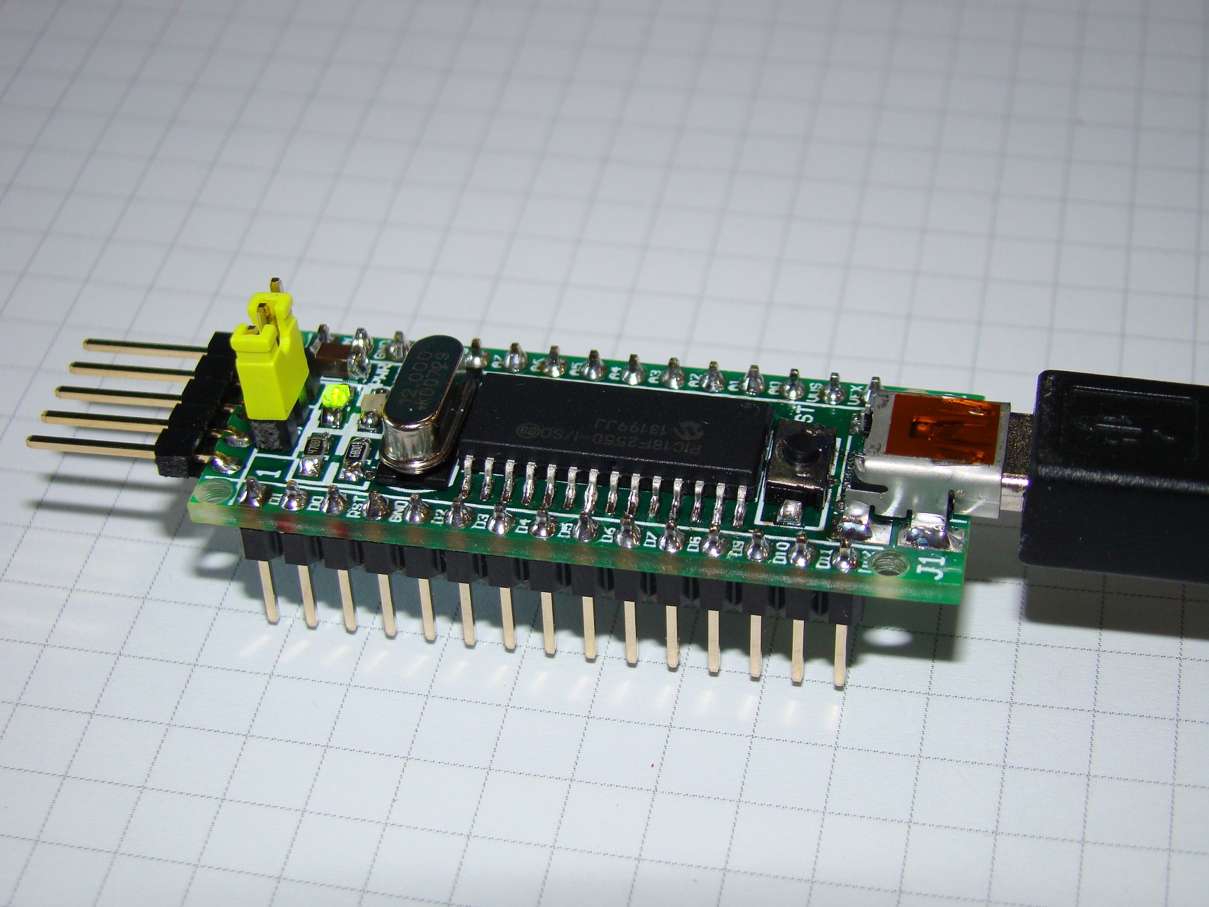
And here’re some photos with the board mounted:
[metaslider id=1137]
- The software
To test the board and validate both the design and the mounting, I make a small program to flash the red led (the classic ‘Hello World’ with leds!!). I use the Mikro C PRO compiler, from MikroElektronika. I like this compiler because offers a lot of libraries with samples and code ready to use. Also, they’ve got a bootloader for this microcontroller (you can download here). So, you can burn the PIC once with the bootload code (using a programming tool) and after you can upload your code to the PIC with a PC tool, eliminating the need of an external programmer!
The code is as simple as you can imagine:
|
1 2 3 4 5 6 7 8 9 10 11 12 13 14 15 16 17 18 19 20 21 22 23 24 25 26 27 28 29 30 31 32 33 34 35 36 37 38 39 40 41 42 43 44 45 46 47 48 49 50 51 52 53 54 55 56 57 58 59 60 61 62 |
/*************************************************************************/ /* SW PRODUCT: PICNANO_HELLO_WORLD */ /* */ /* FILE: PICNANO_HELLO_WORLD.c */ /* CREATION DATE: 26/01/2015 */ /* AUTHOR: Jesus Echavarria Navarro */ /* http://www.jechavarria.com */ /* */ /*---------------------------------------------------------------------- */ /* FILE DESCRIPTION: */ /* */ /* Software to test the PICNANO breacboard. Makes flash the red led */ /* every 500mS. */ /* Based on the PIC18F2550 microcontroller and Mikro C PRO PIC Compiler. */ /* */ /*---------------------------------------------------------------------- */ /* REVIEWS: */ /* */ /* DATE VERSION DESCRIPTION */ /* */ /* 26/01/2015 1.0.0.0 File creation */ /* */ /*************************************************************************/ //======================================================================== // Pinout definition //======================================================================== sbit RED_LED at RC6_bit; //======================================================================== // Main Program //======================================================================== void main() { //----- Minimum setup: Configuring ports --------------------------------- CMCON = 0x07; // Disable comparators ADCON1 = 0x0E; // A0 as an analog input // VREF+ = VDD // VREF- = VSS //----- Ports Settings --------------------------------------------------- TRISA = 0xFF; // Port A as input TRISB = 0x00; // Port B as output TRISC = 0x00; // Port C as output //----- Infinite loop -------------------------------------------------- while (1) { RED_LED = 1; Delay_ms (500); RED_LED = 0; Delay_ms (500); } } |
If you’re interested, here you can download the full project, including the source file, *.hex and config settings: PICNANO_HELLO_WORLD.
Finally, on the Embedded-Lab blog you can find a great article of how to getting started with the PIC18F2550 microcontroller.


This post is also available in: Spanish
i teach a stem club at local middle school. We have a pic kit 3 and I have a couple samples of and 18f2550 left over from an it toy free pcb. Do you have an extra pcb you could share with us for an educational project?
Hi Dan!
Thanks for read the blog and your interest in the board! Unfortunately I’ve all the boards mounted (except oscillator and LDO), so I can’t send you one blank. If you’re interested in one populated, please tell me. Also, you’ve the gerber files in the webpage to manufacture it. If you’re interested in a new fabrication, maybe we can do it together?
Regads from Spain!
I am interested in one populated. I was trying to keep costs down. Would you be able to share one with our club? shipped to US? might be cheaper to fab a pcb domestically. thank you!
Here’s a download link from Oshpark:
https://oshpark.com/shared_projects/ypF3ZLVd
Great project! Did you solder this by hand. Do you have a BOM list with part numbers. I would like to try and build one by hand…
Hi Rando!
Thanks for read the blog and your interest in the board! Also, thanks to upload to Oshpark!
I just update the post with the BOM, I hope this will enough for you and can assemble it. Any questions or doubts, please contact with me. Also, when you finish the building, can you send me a photo?
Thanks again!
Best regards, Jesus
Lovely site, it loads genuinely quick and appears really awesome.
Pingback: PIC18F2550 breakout board - Arduino collector blog
I have a couple of PIC18F2450 – can you advise what they differ from 2550, from the programming point of view? I have a couple of 2450, if the source code for 2550 could be easily modified to run on 2450, your boards design would be perfect fit for me. Could you advise? Thank you very much in advance…
Hi Mac!
First of all, thanks for read the blog and your interest in the board! I just check the datasheet of both microcontrollers, and the differences are mainly in the memory (both FLASH and RAM) and in the internal oscillator. The footprint are the same, so you can use the PICnano breadboard to mount the PIC18F2450 wuithout mods. About the memory, the PIC18F2450 has less Flash (16 kb Flash instead of 32K) and RAM (768 bytes instead of 2048). About the internal oscillator, with the PIC18F2550 you can run up to 8MHz, while using the PIC18F2450 you only can run up to 32 khz. Having this differences in mind, you’ll not have any trouble for porting the code.
I hope the answer clears your question, if you have any other question or doubt, please contact with me!!
Best regards, Jesus
Pingback: PICnano breadboard based on PIC18F2550 -Use Arduino for Projects
Pingback: Designing Electronics in Spain -Use Arduino for Projects
There are other options to achieve the USB module clock requirement and still provide flexibility for clocking the rest of the device from the primary oscillator source.