UPDATE: This board appears on Adafruit’s blog. I’m very happy with this, it’s a great recognition and I only can say Thanks!!!
I’m continuing working with Juan Brito and Danny Macancela from the blog Desafio Ecuador, developing new boards to bring near the technology and programming languages. Our last work is a board to use with the Raspberry Pi and focused to learn Python. The board has the basic elements to start with this language. Also, with the develop of the PCB we remove the wiring, avoiding troubles with connections, inversion polarity…So with this board you only focused in the software develop, because the hardware side will work!
The Hardware
 The RPi Python board is oriented for a educational environment, so the hardware is simple, and has the basic elements to start working with Python. We develop this breakout board to fit in the Raspberry Pi board using the GPIO’s to control the elements. Why Raspberry Pi? Because at this time, is the cheaper and powerfull board in the market. It has a lot of documentation and support behind it, in a future post, I’ll talk about it deeper. If you want more info about the Raspberry Pi now, you can look here, here or here (this last one in Spanish).
The schematics of the board can be download from here: RPI PYTHON BOARD SCHEMATIC
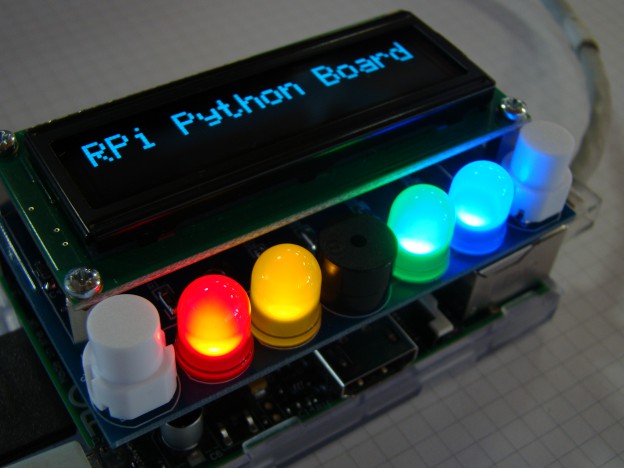
As you can see, the elements that the board includes are the following ones:
- Four 10mm difussed leds:
These leds are the same ones that I use previously on the K4S Keyboard. This leds are connected to a general GIPO’s of the board (see schematic) through a FDV301N mosfet transistor. These transistors are not necessary, because the current on the leds are small, but I prefer put it to protect the GPIO pins of the Raspberry. To activate, you must put the corresponding pin to HIGH, and for turn off, put the pin in LOW level.
- Two pushbuttons:
The pushbuttons allows send inputs to the Raspberry, so reading it you can know if they’re pressed or not and act according it state. By default, when the pushbutton is not pressed, you read a HIGH level, and when you press it, then you will read a LOW level.
- One buzzer:
The buzzer allows you send acoustic signals. You can program a continuous tone or beeps with a variable period, it depends how you program it. Like the leds, I put a MOSFET transistor to protect the Raspberry Pi pin. To activate the buzzer, you must send a HIGH level to the pin. And to turn off, simply send a LOW level!.
- One connector for a 2×16 LCD
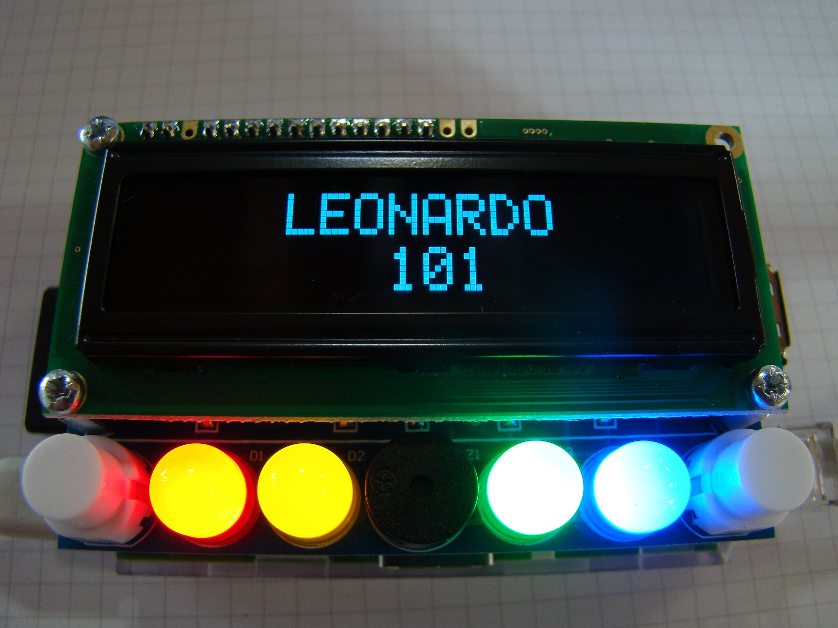
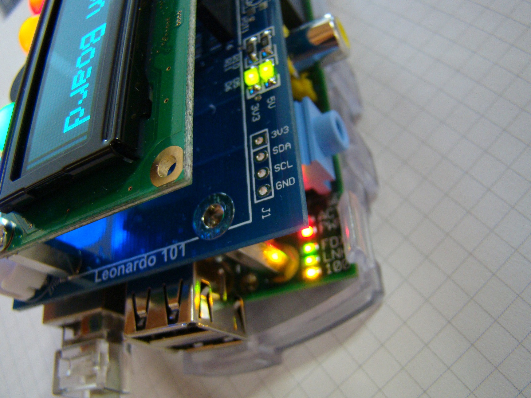
This connector allows to put a standar 2×16 LCD display, to send messages ans show info. You can put a standard LCD module or an OLED one. I decide put this last ones, because are really cool and gives a modern aspect, instead or the traditional ones. And, because the OLED display makes its own light, no backlight is required. This reduces the power required to run the OLED and is why the display has such high contrast. I choose two colours, Red and Blue from Raystar, that also provides a good application note to manage these displays. From here, I want to giving thanks to Jorge Galán, from RC Microelectrónica for his help and support to obtain it.
- One connector for the I2C bus
I put a 4×1 2,54mm standard connector with the I2C signals, to allow connect external peripherals to the Raspberry. In the future, I’m sure I’ll use it!
- Two power leds
Not much to say here, two green leds to indicate that both 5V and 3V3 power supplies of the Raspberry are OK:
 PCB Design
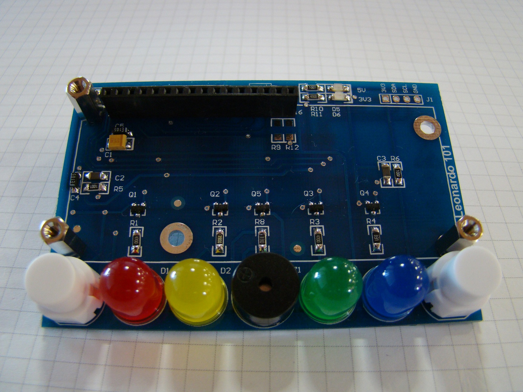
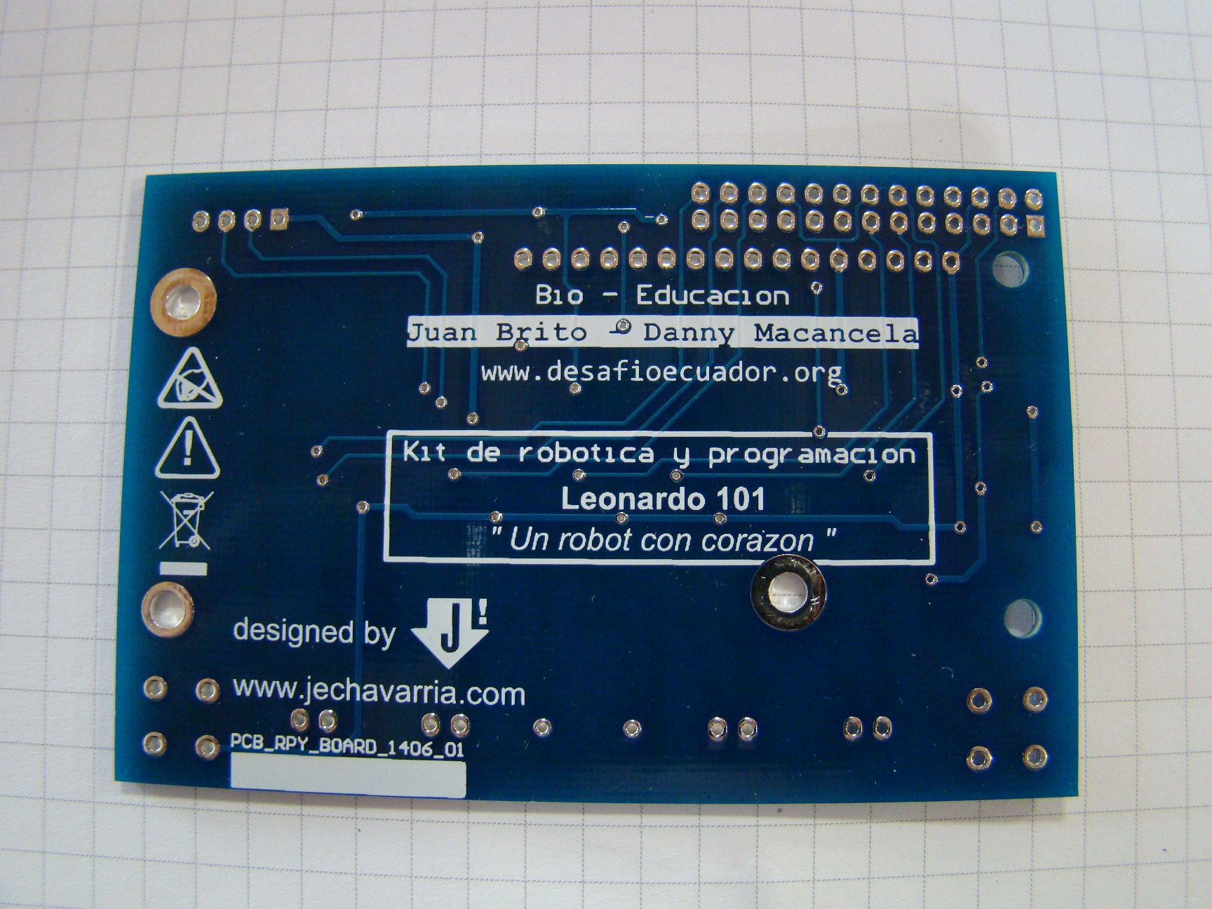
This time I use the Hackvana services to manufacture the boards. I want to check if their boards are as good as the people say. And yes, it’s true, the boards have an excellent quality!! Here’re a couple of photos of the boards without components:

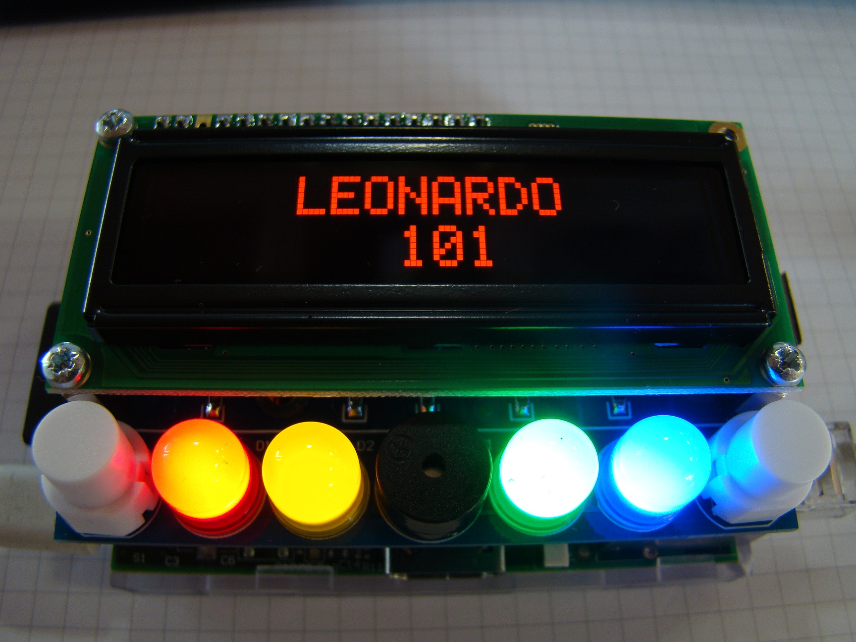
 As usually, I mount the boards by hand. I use 1206 components, only on the top layer, because there aren’t space troubles and 1206 are easy to solder. After mounting the prototype, the next step is fit the board into the Raspberry Pi, to check that all the dimensions are Ok. I use the two holes of the Raspberry to fit the board, using a M2,5×18 spacers from Harwin. For the display, I use three M2,5×11 spacers, from Harwin too. The result is very satisfactory:[metaslider id=1027]
Programming in Python
Once I check that all is Ok, it’s time to start programming. There’re a lot of manuals and references over internet of how to start programming in Python. Here I’ll cover the basic examples to start working with the board. I assume you have a Raspberry Pi with a installed distribution. I use Raspbian to work with the board, this distribution includes by default the Python compiler and S4A, that allows work with the K4S board I cover previously. Below are the basic examples to start working with Python and the board:
|
1 2 3 4 5 6 7 8 9 10 11 12 13 14 15 16 17 18 19 20 21 22 23 24 25 26 27 28 29 30 31 32 33 34 35 36 37 38 39 40 |
#!/usr/bin/env pyth # # RPi Board - Sample 01: Turn on the green led # # Author : jechavarria # Site : www.jechavarria.com # : www.desafioecuador.org # # Date : 01/10/2014</p> # Library to use the GPIO pins on Raspberry Pi import RPi.GPIO as GPIO # Define GPIO for led mapping (USES BCM MODE NUMBERING scheme) GREEN_LED = 25 # Define main routine def main(): GPIO.setwarnings(False) GPIO.setmode(GPIO.BCM) GPIO.setup(GREEN_LED,GPIO.OUT) GPIO.output(GREEN_LED,False) while 1: GPIO.output(GREEN_LED, True) # =================================================================== # Ensure that the GPIO is cleaned up whichever way the program exits # This avoids all those annoying "channel already in use" errors if __name__ == '__main__': try: main() finally: GPIO.cleanup() # =================================================================== |
|
1 2 3 4 5 6 7 8 9 10 11 12 13 14 15 16 17 18 19 20 21 22 23 24 25 26 27 28 29 30 31 32 33 34 35 36 37 38 39 40 41 42 43 44 45 46 47 48 49 |
#!/usr/bin/env pyth # # RPi Board - Sample 02: Makes blink the green led # # Author : jechavarria # Site : www.jechavarria.com # : www.desafioecuador.org # # Date : 01/10/2014 # Library to use the GPIO pins on Raspberry Pi import RPi.GPIO as GPIO import time # Define GPIO for led mapping (USES BCM MODE NUMBERING scheme) GREEN_LED = 25 # Define main routine def main(): GPIO.setwarnings(False) GPIO.setmode(GPIO.BCM) GPIO.setup(GREEN_LED,GPIO.OUT) GPIO.output(GREEN_LED,False) while 1: GPIO.output(GREEN_LED, True) time.sleep(1) GPIO.output(GREEN_LED, False) time.sleep(1) # =================================================================== # Ensure that the GPIO is cleaned up whichever way the program exits # This avoids all those annoying "channel already in use" errors if __name__ == '__main__': try: main() finally: GPIO.cleanup() # =================================================================== |
|
1 2 3 4 5 6 7 8 9 10 11 12 13 14 15 16 17 18 19 20 21 22 23 24 25 26 27 28 29 30 31 32 33 34 35 36 37 38 39 40 41 42 43 44 45 46 47 48 49 50 51 |
#!/usr/bin/env pyth # # RPi Board - Sample 03: Makes a beep of 0,5 secs # # Author : jechavarria # Site : www.jechavarria.com # : www.desafioecuador.org # # Date : 01/10/2014 # Library to use the GPIO pins on Raspberry Pi import RPi.GPIO as GPIO import time # Define GPIO for led mapping (USES BCM MODE NUMBERING scheme) GREEN_LED = 25 BUZZER = 27 # Define main routine def main(): GPIO.setwarnings(False) GPIO.setmode(GPIO.BCM) GPIO.setup(GREEN_LED,GPIO.OUT) GPIO.setup(BUZZER,GPIO.OUT) GPIO.output(GREEN_LED,False) GPIO.output(BUZZER,True) time.sleep(0.5) GPIO.output(BUZZER,False) while 1: # Do nothing time.sleep(1) # =================================================================== # Ensure that the GPIO is cleaned up whichever way the program exits # This avoids all those annoying "channel already in use" errors if __name__ == '__main__': try: main() finally: GPIO.cleanup() # =================================================================== |
|
1 2 3 4 5 6 7 8 9 10 11 12 13 14 15 16 17 18 19 20 21 22 23 24 25 26 27 28 29 30 31 32 33 34 35 36 37 38 39 40 41 42 43 44 45 46 47 48 49 50 51 52 53 54 55 56 57 58 59 60 61 62 63 64 65 66 67 68 69 70 71 72 73 74 75 |
#!/usr/bin/env pyth # # RPi Board - Sample 04: Reading pushbuttons # When left button is pressed, the blue led turns on # and when releases, the blue led turns off! # # Author : jechavarria # Site : www.jechavarria.com # : www.desafioecuador.org # # Date : 01/10/2014 # Library to use the GPIO pins on Raspberry Pi import RPi.GPIO as GPIO import time # Define GPIO for led mapping (USES BCM MODE NUMBERING scheme) GREEN_LED = 25 BLUE_LED = 8 BUZZER = 27 LEFT_PUSH = 4 RIGHT_PUSH = 7 # Define main routine def main(): GPIO.setwarnings(False) GPIO.setmode(GPIO.BCM) # Configure the outputs GPIO.setup(GREEN_LED,GPIO.OUT) GPIO.setup(BLUE_LED,GPIO.OUT) GPIO.setup(BUZZER,GPIO.OUT) # Configure the inputs GPIO.setup(LEFT_PUSH,GPIO.IN) GPIO.setup(RIGHT_PUSH,GPIO.IN) # Initialize the outputs GPIO.output(GREEN_LED,False) GPIO.output(BLUE_LED,False) GPIO.output(BUZZER,False) # Initial beep (100ms beep) GPIO.output(BUZZER,True) time.sleep(0.1) GPIO.output(BUZZER,False) while 1: if (GPIO.input(LEFT_PUSH) == False): GPIO.output(BLUE_LED,True) else: GPIO.output(BLUE_LED,False) # =================================================================== # Ensure that the GPIO is cleaned up whichever way the program exits # This avoids all those annoying "channel already in use" errors if __name__ == '__main__': try: main() finally: GPIO.cleanup() # =================================================================== |
|
1 2 3 4 5 6 7 8 9 10 11 12 13 14 15 16 17 18 19 20 21 22 23 24 25 26 27 28 29 30 31 32 33 34 35 36 37 38 39 40 41 42 43 44 45 46 47 48 49 50 51 52 53 54 55 56 57 58 59 60 61 62 63 64 65 66 67 68 69 70 71 72 73 74 75 76 77 78 79 80 81 82 83 84 85 86 87 88 89 90 91 92 93 94 95 96 97 98 99 100 101 102 103 104 105 106 107 108 109 110 111 112 113 |
#!/usr/bin/env pyth # # RPi Board - Sample 05: Shifting leds # When left button is pressed, the leds turn on and # off from left to right every 0.5 secs. # When right button is pressed, the leds turn on and # off from right to left every 0.5 secs. # # Author : jechavarria # Site : www.jechavarria.com # : www.desafioecuador.org # # Date : 01/10/2014 # Library to use the GPIO pins on Raspberry Pi import RPi.GPIO as GPIO import time # Define GPIO for led mapping (USES BCM MODE NUMBERING scheme) GREEN_LED = 25 BLUE_LED = 8 RED_LED = 18 YELLOW_LED = 17 BUZZER = 27 LEFT_PUSH = 4 RIGHT_PUSH = 7 # Define main routine def main(): GPIO.setwarnings(False) GPIO.setmode(GPIO.BCM) # Configure the outputs GPIO.setup(GREEN_LED,GPIO.OUT) GPIO.setup(BLUE_LED,GPIO.OUT) GPIO.setup(RED_LED,GPIO.OUT) GPIO.setup(YELLOW_LED,GPIO.OUT) GPIO.setup(BUZZER,GPIO.OUT) # Configure the inputs GPIO.setup(LEFT_PUSH,GPIO.IN) GPIO.setup(RIGHT_PUSH,GPIO.IN) # Initialize the outputs GPIO.output(GREEN_LED,False) GPIO.output(BLUE_LED,False) GPIO.output(RED_LED,False) GPIO.output(YELLOW_LED,False) GPIO.output(BUZZER,False) # Initial beep (100ms beep) GPIO.output(BUZZER,True) time.sleep(0.1) GPIO.output(BUZZER,False) while 1: if (GPIO.input(LEFT_PUSH) == False): GPIO.output(RED_LED,True) time.sleep(0.5) GPIO.output(RED_LED,False) GPIO.output(YELLOW_LED,True) time.sleep(0.5) GPIO.output(YELLOW_LED,False) GPIO.output(GREEN_LED,True) time.sleep(0.5) GPIO.output(GREEN_LED,False) GPIO.output(BLUE_LED,True) time.sleep(0.5) GPIO.output(BLUE_LED,False) if (GPIO.input(RIGHT_PUSH) == False): GPIO.output(BLUE_LED,True) time.sleep(0.5) GPIO.output(BLUE_LED,False) GPIO.output(GREEN_LED,True) time.sleep(0.5) GPIO.output(GREEN_LED,False) GPIO.output(YELLOW_LED,True) time.sleep(0.5) GPIO.output(YELLOW_LED,False) GPIO.output(RED_LED,True) time.sleep(0.5) GPIO.output(RED_LED,False) # =================================================================== # Ensure that the GPIO is cleaned up whichever way the program exits # This avoids all those annoying "channel already in use" errors if __name__ == '__main__': try: main() finally: GPIO.cleanup() # =================================================================== |
In a future entry, I’ll put the code to show messages in the OLED display, because these code is more complex and requires more technical knowledge.
Happy debugging!!


This post is also available in: Spanish
Are these boards available somewhere. Great project.
Thanks
Hi Paul!
First of all, thanks for read the blog and your interest in the project. Actually, we only have two populated prototypes. At the end of this month, we expect to have some boards in stock and have the price for it. Can you wait until then? Some questions: will you interested in a blank board oor do you want a fully assemble one? And how many boards will you want / need?
Thanks again and sorry for not have the boards yet, I hope the delay will not be a trouble. Please contact with me for any question or suggestion!!
Best regards, Jesus
I’m interested in a completed board. What is the cost?
I’m interested in a completed board. What is the cost?
Pingback: RPi Board: A board to learn Python with the Raspberry Pi #piday #raspberrypi @Raspberry_Pi « adafruit industries blog
Will these boards work with the B+ board variant and are/will there be left over GPIO pins to be used for other purposes?
This board amalgamates the functionality I wish to have in a small project I have in mind related to the production of maple syrup temperature monitoring.
Hi Ron!
Thanks for your interest in the board. Yes, I test these days and the board works fine with the B+ model. But I’m having some troubles with the OLED driver in this B+ version, I’m working on it. But it works perfect with a normal LCD display!
Best regards, Jesus
I’m interested in these boards, specifically for both learning Python and integrating them into IoT projects in my home. Do you have an anticipated “for sale” date yet? And do you plan to sell them on Tindie?
Thanks for this great project!
Nice job! I would be very interested in at least one of these boards. Any ideas when they will be available for purchase?
Thanks
Pingback: RPi Raspberry Pi Breakout Board Designed To Help You Learn Python
Pingback: An Add-on Board for Learning Python with Raspberry Pi - DIGX Tech Solutions
This is really nice. I personally think the RPi is a much better platform for learning programming because you can do more with it, using Python or Scratch.
One feature request for this wonderful board – I always find that having more interesting inputs help motivate the programmers. How about adding a sound or a light (LDR) input option? This is what makes the littleRobotFriend and the PicAxe school experiment board (axe092) so nice.
Hi PK! First, thanks for read the blog and your friendly comment! I just see the littleRobotFriend, and they’re lovely!! About your suggestions, I also think in these two elements for a new version of the Scratch board (and I also will include a motor driver!). Unfortunately, for the Python board these elements are difficult to integrate, because these are analog signals, and the Raspberry doesn’t include an on-board ADC. Of course, these signals can be included, but then we need an external ADC for the LRD and a DAC for the speaker, and these elements makes the code more complex. But it’s a good idea, maybe for an advanced board to program Python!
Thanks again for your interest and comments!!
Best regards, Jesus
Jesus,
Thanks for the explanation ! I didn’t realized there is not ADC/DAC support on the GPIO pins. Now i understand no-one put analog type I/O on the basic expansion boards, and offer i2c versions instead.
Like to see you make this board work with the 18-Pin LCD so you can have RGB control.
Pingback: Tindie Blog | Holiday Gifts for Little Makers