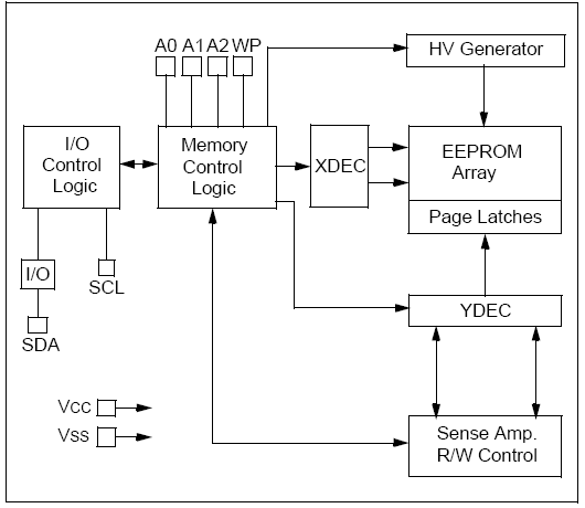
I resume this brief series of articles with another device I usually use. It’s the popular 24LC256 I2C EEPROM memory, from Microchip. First of all, you can find the datasheet here. This memory has a 32K x 8 bytes of capacity (36768 bytes if you prefer), and can works between 1.7V to 5.5V, with a maximun clock frequency of 1MHz (FC model with Vcc > 2.5V). Of course, it’s compatible with the 100khz and 400khz standard speeds. Here’s a block diagram of this memory:
General Features
This memory has three pins to configure the device address (A0, A1 and A2). So, you can use up to eight memories (only two with the MSOP package) in the same bus, wich gives you a total capacity of 256KB (using this memory model). To set the device address, you only must connect these pins to VCC or VSS. The form of set the device address is the next one:
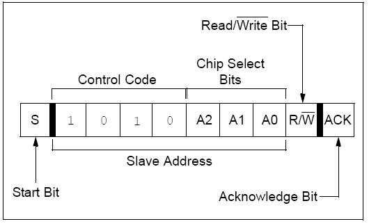
For example, if you tied A0, A1 and A2 to VSS, the device address will be:
- For write operations: 1010 (control code) + 000 (A2, A1, A0 value) + 0 (write) –> 0xA0
- For read operations: 1010 (control code) + 000 (A2, A1, A0 value) + 1 (read) –> 0xA1
Usually, these pins are hard-wired to high and/or low levels. If you want to control these pins with a microcontroller, FPGA or something similar, please be sure that these pins are driven to ‘0’ or ‘1’ levels before access to the memory.
Other pin of this memory is the WP. This pin is used to write – protect the entrie EEPROM array. If the pin is tied to VSS, then the write protecction is disabled. If this pin is tied to VCC, then the write protection is enabled, but read operations are not affected.
Device addressing
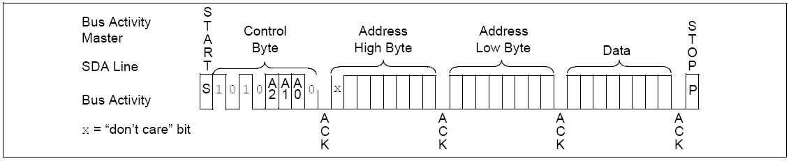
This memory has 32KB of data. This means that the address will be from 0x0000 to 0x7FFF, and you need 15 bits to address it. So, the sequence to access to an specific address in the EEPROM array consist in:
- Generate the Start condition in the I2C bus (SDA low, then SCL low).
- Send the device address (0xA0 or 0xA1 if continuing with the example above)
- Send the high byte of the address to access
- Send the low byte of the address to access.
Assuming general functions to access the I2C bus, this will be the sequence to access at the 0x0100 position:
|
1 2 3 4 5 6 7 8 9 |
#define EEPROM1_WR 0xA0 // 24LC256 Address to write #define EEPROM1_RD 0xA1 // 24LC256 Address to read I2C1_Start (); // I2C Start condition I2C1_Write (EEPROM1_WR); // 24LC256 address I2C1_Write (0x01); // High byte to access (from 0x00 to 0x7F) I2C1_Write (0x00); // Low byte to access (from 0x00 to 0xFF) |
Write Operations
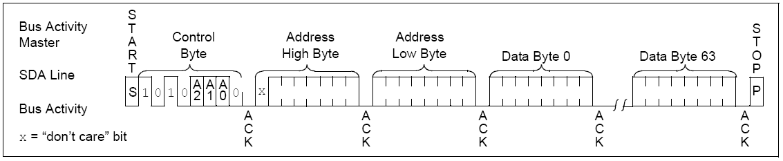
This memory has two write modes: byte write and page write. In byte write mode, you first set the address position where you want to write (using the above sequence). Then, the next byte will be the data that you want to store. And, finally, you must send the Stop condition. In the datasheet you can find this sequence as follows:
 And her’s a sample code to write in the 0x0060 the ‘0xAA’ value:
|
1 2 3 4 5 6 7 8 9 10 11 12 |
#define EEPROM1_WR 0xA0 // 24LC256 Address to write #define EEPROM1_RD 0xA1 // 24LC256 Address to read I2C1_Start (); // I2C Start condition I2C1_Write (EEPROM1_WR); // 24LC256 address I2C1_Write (0x00); // High byte to access (from 0x00 to 0x7F) I2C1_Write (0x60); // Low byte to access (from 0x00 to 0xFF) I2C1_Write (0xAA); // Value 0xAA store in the 0x0060 position I2C1_Stop (); |
In the page write mode, after send the first byte of data, you can send up to 63 more data bytes (to complete a 64-byte page) until the Stop condition. In these moment, the memory starts an internal write cycle, and when finished, the internal address point increments automatically.
And here’s an example to write the ‘buffer’ array starting in the 0x0200 address position:
|
1 2 3 4 5 6 7 8 9 10 11 12 13 14 15 16 17 18 19 20 |
#define EEPROM1_WR 0xA0 // 24LC256 Address to write #define EEPROM1_RD 0xA1 // 24LC256 Address to read unsigned char buffer [64]; unsigned char i; for (i=0; i<64; i++) buffer [i] = i; // Initial value I2C1_Start (); // I2C Start condition I2C1_Write (EEPROM1_WR); // 24LC256 address I2C1_Write (0x02); // High byte to access (from 0x00 to 0x7F) I2C1_Write (0x00); // Low byte to access (from 0x00 to 0xFF) for (i=0; i<64; i++) I2C1_Write (buffer [i]);// Stores 'buffer' array starting in the 0x0200 position I2C1_Stop (); |
Some important things about writting process:
- The write cycle time is max. 5ms. This means that you must wait this time before consecutive access, regardless read or write modes.
- This time is the same for both byte and page write modes. This is because when you write less than 64 bytes, the rest of the data in the page is refreshed along with the data bytes being written.
- If you send more than 64 bytes, the result is that the data will wraps around to the beginning of the current page, instead of start writting in the following page. So have this in mind when you want to write more than 64 bytes.
Read Operations
For read operations, you can read all the bytes that you want, from only one to all the entrie memory. The read process is similar to the write one. The first step is set the address that you want to read. To do this, the process is the same shown above:
|
1 2 3 4 5 6 7 8 9 |
#define EEPROM1_WR 0xA0 // 24LC256 Address to write #define EEPROM1_RD 0xA1 // 24LC256 Address to read I2C1_Start (); // I2C Start condition I2C1_Write (EEPROM1_WR); // 24LC256 address I2C1_Write (0x00); // High byte to access (from 0x00 to 0x7F) I2C1_Write (0x00); // Low byte to access (from 0x00 to 0xFF) |
Now, you must repeat the Start condition, and send the read control byte:
|
1 2 |
I2C1_Start (); // Repeat I2C Start condition I2C1_Write (EEPROM1_RD); // 24LC256 address to read process |
After this command, the memory is ready to start the read process. After each byte you read, you must send an ACK, as you can see in the datasheet:
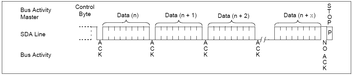
To finish the reading process, you must send a NACK followed by the Stop condition.
Here’s an example of source code to read one page of data from the EEPROM:
|
1 2 3 4 5 6 7 8 9 10 11 12 13 14 15 16 17 18 19 20 21 22 23 24 25 |
#define EEPROM1_WR 0xA0 // 24LC256 Address to write #define EEPROM1_RD 0xA1 // 24LC256 Address to read unsigned char buffer [64]; unsigned char i; I2C1_Start (); // I2C Start condition I2C1_Write (EEPROM1_WR); I2C1_Write (0x00); // Read first page (positions 0-63) I2C1_Write (0x00); I2C1_Start (); // Repeat Start Condition I2C1_Write (EEPROM1_RD); // Time to read for (i=0; i<63; i++) { buffer [i] = I2C1_Read (); I2C1_txACK (); } buffer [63] = I2C1_Read (); // Last byte: Send NACK I2C1_txANCK (); I2C1_Stop (); |


thankyou a very sir …. pretty compact explanation
hello sir, thanks for your fantastic explanation… this is absolutely nice work. keep going…
Thanks for this presentation, it does help me a little. What i am trying to do is to write and read byte to this eeprom, using an arduino, but I want to use a software i2c library (not the Wire.h library).
I tried different libraries (SoftI2CMaster and I2cMaster) and it does not work at all.
Does your sample use a software or hardware feature?
It does not look like Arduino code? What is it for?
Any advice for me?
Thanks.
Hi Frederic!
First of all, thanks for read the blog and your interest in the post. About your inquiry, some tips. The code you see in the web is for an Atmel 8051 core, AT89C51RE2, that I use in this board:
To manage the EEPROM on this board, I also use an I2C software communication. I use as a reference the following Keil info: http://www.keil.com/i2c/examples.asp.
With the software routines, you must have in mind few things. The most important are the times, to ensure good Start and Stop conditions. Also, ensure that you send the ACK or NACK when finish the communications. And also ensure that between a write and a read you must leave at least 5ms.
If you can specify a bit more your troubles with the code, maybe I can help you a bit more. So don’t heistate in contact with me to try to solve your issues!
Best regards from Spain!!
I am trying with same logic for Ti Digital signal controller TMS320F28027
But it is not working
I have connected 5.6kohms for SDA and SCL pull up to 3.3 volt
and I am working for 300kHz
And also I have deactivated the internal pull up of the SDA and SCL of microcontroller
But it is not working
Please guide
Hi Ashutosh:
First of all, thanks for read the blog and your interest in the article. It seems that your setup is correct, I don’t find nothing strange.
I can give you some points to investigate:
– Check the WP pin. It must tied to VSS for write operations.
– Check the time between write and read cycles. After a write operation, you must wait at least 5ms to read the memory.
– Ensure the address of the memory in the I2C bus is correct
– Before a read operation, ensure that you send the correct address to read the byte you want.
At this time and without the code, I can’t help you more that with these tips. I hope this serves you!
Best regards from Spain!
need help to program eprom give me guide simple and some examples
thanks
Hi!
Can you give me more info about your project, setup, application? It’s very difficult answer a generic question like the one you propose.
Regards, Jesus
Hi Jesus Echavarria
First thank you so much for your time to writing this helpful page,
Please Could you possible posts other code for Picaxe ?
Sincerely Thank you
lam
Hi Iam!
First, thanks for read the blog and your interest on the post. Unfortunately I never work before with Picaxe, so I can’t give you any example. But if you send me some code that manages the IO lines, sure we can do an example to manage it.
Regards, Jesus
Dear Sir
First thanks a lot for your enthusiasm reply .
Since long time I would like write and read with eeprom 24c16 or
24c256 (just a few bit or byte for start learning) by write read 1 or 0 (external data ) .But with my too low basic numeric and programmer and bad English I cannot to do that.
EXp : Write 1 (high) to 24cxx >>>> Read data by see led (on) at data out of 24c xx.
OR
Write 0 (low) to 24c xx >>>> Read data by see led (off) at data out of 24cxx.
[[[[[[[[[[[[[[[[[[[[[[[[[[[[[[[[[[
Sir, I saw on youtube :
I2C Bit-Banged without Microcontroller!
Kevin Darrah
https://www.youtube.com/watch?v=8ZYMrcHm91s
It exact as I wish to do but unfortunate with my poor English I can’t do it as him guide. So when you have the time please help me to got a code read write a few bit or byte with DATA= =1 and DATA = 0 for easy compare
Exp : X=1 or 0 //// Data =1 or 0
Write :
clock:xxxxxxxxxxxxxxxxxxxxxx……….
start xxxxxxxxxxxxxxxxxxxxxxxxxx stop
Read:
clock xxxxxxxxxxxxxxxxxxxxxx
Start xxxxxxxxxxxxxxxxxxxxxxxx stop
==========================
instead of use button i will try to use picaxe code ( not yet don’t know how do it) or trigger switch for anti bouncing . Hope you understand what I wish and help me or give me your opinion ,if possible send email to me please .Thank you so much in advance for you time,
Sincerely yours
lam (CANADA)
goood explanation
Thanks! I hope this will useful for you! If you have any question or doubt, please contact with me!
Hello dear jechavarria,
I wrote a programme for read and write data in EEprom At24c64.
I wrote my code here:
//——————————————————————————
void write_eeprom (void)
{
Soft_I2C_Start();
Soft_I2C_Write(EEPROM1_WR);
Soft_I2C_Write (0x00); //high byte
Soft_I2C_Write (0x00); //low byte
Soft_I2C_Write(0x55); //My Value
Soft_I2C_Stop();
}
//——————————————————————————
void read_eeprom (void)
{
Soft_I2C_Start();
Soft_I2C_Write(EEPROM1_WR);
Soft_I2C_Write (0x00); // High byte
Soft_I2C_Write (0x00); // Low byte
Soft_I2C_Start();
Soft_I2C_Write(EEPROM1_RD);
delay_ms(5);
take = Soft_I2C_Read(0); // Read data and send the not_acknowledge signal
Soft_I2C_Stop();
}
I want to know that is my code true and without any problem?
and also why in reading procedure we have to start with [Soft_I2C_Write(EEPROM1_WR);] ???
Thanks and i am waiting for your reply.
Sadeghi
Good day Sadeghi!
First of all, thanks for read the blog and your interest on it. Answering your question, at first look the code seems ok. I check the datasheet of the memory and you follow the steps that’s describe on it (http://www.atmel.com/images/doc0336.pdf) pages 11 and 12. In the read procedure, you start with Soft_I2C_Write(EEPROM1_WR) because you must fix the address of the memory where you want to start read. Is for set the initial address, after it and send the address, you start with the read procedure.
I hope this serves you, try to test it and tell me!!
Best regards, Jesus
Dear jechavarria,
Thank you so much for your response.
I will test my code and will tell you.
Best Regards.
Sadeghi
Ok, keep me informed! Anything more you need tell me!
Best regards, Jesus
Dear jechavarria,
Thanks for this excellent article.
I have tested the code and it works great.
However, I am getting a problem.
I am writing to memory from address 0x0000. Now I am inserting six characters one by one(‘A’,’B’, upto ‘F’; Hex values from 0x41 to 0x46).
Now when I am reading them back, from address 0x0000, I am getting first character NULL (Hex value 0x00).
So if I want to read all six characters, I have to perform read operation seven times.
Am I doing anything wrong or am I missing a concept? Help me on this.
Thanks in advance.
Good day Rahul, thanks for your comment. It seems that you have any trouble changing from write to read operations. To read 6 characters, you need only six read operations, not seven. Without the code, I only can give you some points to check. First, ensure that after the last write you let at least 5ms before start reading. On the reading process, remember that first you must make a write operation to set the address, at 0x0000 position. Check this and, if you want, send me the code to check it!
Best regards, Jesus
Hi sir ;
Thanks for your great work.But i m very new to embedded coding actually my project is “read and write operation in I2C EEPROM (AT24CM024) for LPC2378”.I want to know more about this project my only worry is i m so new to this embedded coding.Can you help me to do this coding. not only this coding i want to know more. I thought this is my begining.
Thanks in advance
Thanks for this!!
I am learning i2C on STM32 ARM, and with very little background. You provided me all the info I needed to be up and running with working code.
Hi Keith! Thanks for your words, I hope the post helps you in your project. If you need something more just tell me 😉
Best regards from Spain!
Hello,Sir I am working on STM32F103C8 board and trying to access EEPROM AT24C64. Following is my code will you please help me solving issue in yhis code?
Here when I Read Data From Memory after writing it reads fine but after giving delay of few seconds it gives me value 8 every time. I am using HAL Library for this purpose.
My code is Here…..
void StartDefaultTask(void const * argument)
{
/* USER CODE BEGIN 5 */
/* Infinite loop */
for(;;)
{
EEPROM_Write_Byte(Setting_Temp_300022,a);
HAL_GPIO_WritePin(GPIOB,GPIO_PIN_12,GPIO_PIN_SET);
b=EEPROM_Read_Byte(Setting_Temp_300022);
HAL_GPIO_WritePin(GPIOB,GPIO_PIN_12,GPIO_PIN_SET);
osDelay(1000);
c=EEPROM_Read_Byte(Setting_Temp_300022);
HAL_GPIO_WritePin(GPIOB,GPIO_PIN_12,GPIO_PIN_RESET);
}
/* USER CODE END 5 */
}
and EEPROMFUnctions are as follows ……
void EEPROM_Write_Byte(uint16_t RegAdd,uint8_t data)
{
HAL_I2C_Mem_Write(&EEPROM_I2C,EEPROM_ADD,RegAdd,2,(uint8_t *)&data,3,1);
HAL_Delay(10);
}
uint8_t EEPROM_Read_Byte(uint16_t RegAdd)
{
char data;
HAL_I2C_Mem_Read(&EEPROM_I2C,EEPROM_ADD,RegAdd,2,(uint8_t *)&data,1,1);
return data;
}
Hello Sir,
I want to make a push button counter with the help of Arduino Uno and 24lc512.
i want to use 24LC512 for last button count value. is it possible then please help me with code.